Structure of fan devices for leading out wires

a technology of fan device and lead wire, which is applied in the direction of positive displacement liquid engine, piston pump, instruments, etc., can solve the problems of small windage loss and contact between wires and impellers, and achieve the effect of minimizing windage loss and small windage loss

Inactive Publication Date: 2005-08-18
NIPPON DENSAN CORP
View PDF9 Cites 24 Cited by
  • Summary
  • Abstract
  • Description
  • Claims
  • Application Information

AI Technical Summary

Benefits of technology

[0009] An object of the present invention is to provide a fan device that is capable of supplying a large quantity of air and has a small wi

Problems solved by technology

Therefore, a fan device is realized that has little possibility t

Method used


Image

  • Structure of fan devices for leading out wires
  • Structure of fan devices for leading out wires
  • Structure of fan devices for leading out wires

Examples


first embodiment

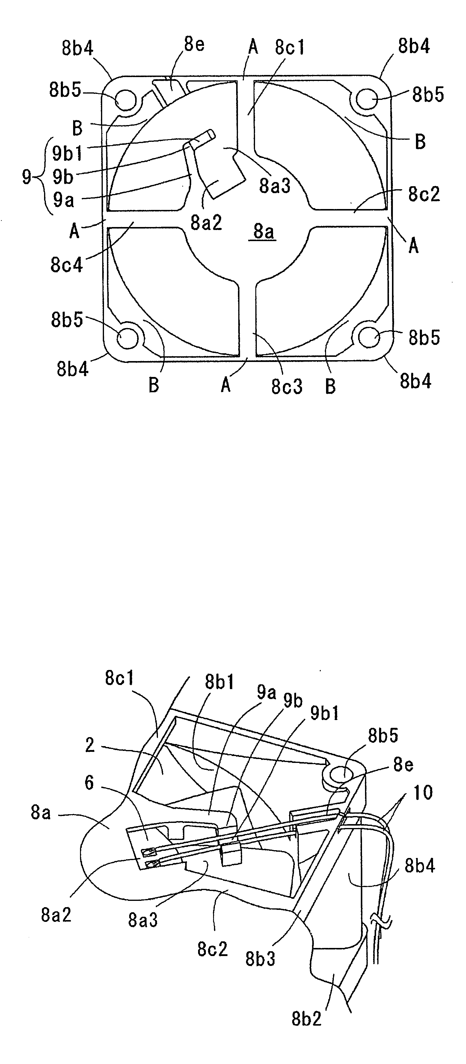
[0046] In the fan device according to this embodiment, the lead wire is led out not through the support beams 8c1-8c4 but through the space between the same and the motor support portion 8a. Furthermore, the fan device of this embodiment has the same feature as the fan device of the first embodiment in that the lead wire retaining portion 29 is positioned at the motor support portion 8a side. Particularly, as the lead wire retaining recess 29b is supported by the two arm portions 29a1 and 29a2, the lead wire retaining portion 29 has a high rigidity and is fixed to the motor support portion 8a securely. Thus, the housing 8 itself or the completed fan device is resistant to be broken even if a certain obstacle comes into collision with the lead wire retaining portion 29.

[0047] Next, a fan device according to a third embodiment of the present invention will be described mainly about the difference from the first embodiment with reference to FIG. 5. FIG. 5 shows a bottom view of the hou...

third embodiment

[0052] In the fan device according to this embodiment, the lead wire is led out not through the support beams 8c1-8c4 but through the space between the same and the motor support portion 8a. The fan device of this embodiment has the same feature as the fan device of the third embodiment in that the lead wire retaining portion 49 is positioned at the fan outer frame portion side. However, especially the two arm portions 49a1 and 49a2 support the lead wire retaining recess 49b, so the lead wire retaining portion 49 has a high rigidity and is fixed to the motor support portion 8a securely. Thus, the housing 8 itself or the completed fan device is resistant to be broken even if a certain obstacle comes into collision with the lead wire retaining portion 49.

[0053] Though preferred embodiments for implementing the fan device according to the present invention are described above, the present invention is not limited to these embodiments and various modifications is possible in the scope o...


PUM


Abstract

A lead wire is led out to a fan outer frame portion side through a lead wire retaining portion that is provided to a motor support portion of a housing that fixes a fan motor so as to protrude to a fan outer frame portion side or is provided to the fan outer frame portion of the housing so as to protrude to the motor support portion side. The lead wire retaining portion is positioned between neighboring support beams for fixing the motor support portion to the fan outer frame portion.

Description

BACKGROUND OF THE INVENTION [0001] 1. Field of the Invention [0002] The present invention relates to a structure of a fan device for leading out lead wires. Fan devices are used for various apparatuses such as office machines or home appliances. [0003] 2. Description of the Prior Art [0004] Fan devices are used widely in various apparatuses such as office machines or home appliances for cooling heat that is generated when the apparatuses operate. In particular, a personal computer or a server device requires a high efficiency fan device having a small size and being capable of supplying large quantity of air in proportion to the processing speed and the requirement for smaller size thereof, which make a CPU chip and other ICs generate more heat during operation. A fan device usually comprises a fan motor, a housing and a printed circuit board. The fan motor comprises a motor for generating a driving force and an impeller that is rotated by the driving force for generating a cooling ...

Claims


Application Information

Patent Timeline
IPC IPC(8): F04D29/00F04B17/00F04B35/04F04D25/08G06F1/20H02K5/22
CPCF04D25/0693F04D25/08
Inventor TAKAHASHI, SHUJIINOUE, TOMOYUKI
Owner NIPPON DENSAN CORP
Why Eureka
Try Eureka