
Method for the direct call of a function by a software module by means of a processor with a memory-management unit (MMU)

a memory management unit and function technology, applied in multi-programming arrangements, program control, instruments, etc., can solve the problems of inability to achieve the highest possible data throughput, inability to arbitrarily force tasks to use shared memory, and inability to exchange data between tasks

Inactive Publication Date: 2005-08-18
NAT INSTR IRELAND RESOURCES
View PDF4 Cites 6 Cited by
  • Summary
  • Abstract
  • Description
  • Claims
  • Application Information

AI Technical Summary

Benefits of technology

Enables direct and immediate exchange of data and events between tasks with high determinability and throughput, bypassing the limitations of memory isolation and operating system dependencies, while ensuring safe and predictable execution.

Problems solved by technology

Data exchange between tasks is made impossible by memory isolation.
Data exchange through an operating system has the disadvantage that the highest possible data throughput is not achievable due to the copying of the data.
This contradiction is not problematic, however, because it is not possible to arbitrarily force tasks to use shared memory.
The exchange of events over an operating system has the disadvantage that the time of the transfer depends on the operating system and the other tasks executed by the operating system.
Thus, it is not possible to perform an exchange of events with optimum determinability, i.e., with certainty of the time point of the transfer.
However, no current operating system offers such a mechanism.

Method used


Image

  • Method for the direct call of a function by a software module by means of a processor with a memory-management unit (MMU)
  • Method for the direct call of a function by a software module by means of a processor with a memory-management unit (MMU)
  • Method for the direct call of a function by a software module by means of a processor with a memory-management unit (MMU)

Examples


Embodiment Construction

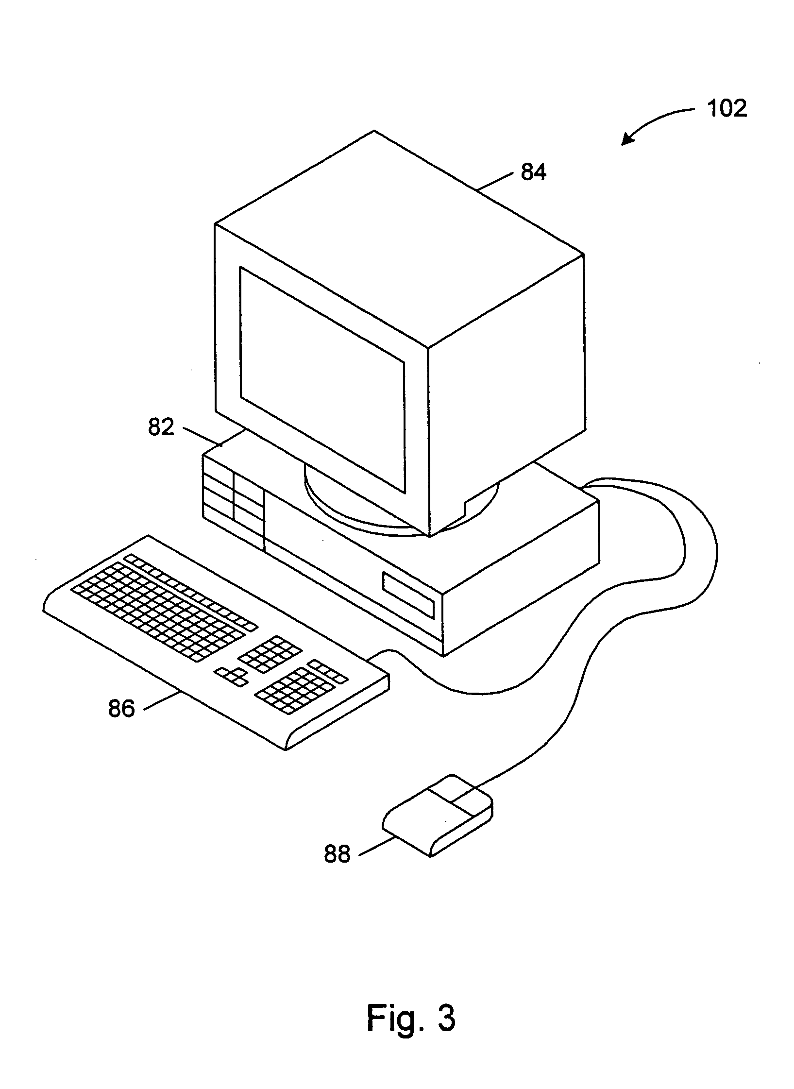
[0026]FIG. 3—Exemplary Computer System

[0027]FIG. 3 illustrates an exemplary computer system 102 which may include one embodiment of the invention. One embodiment of the present invention operates in a computer system 102. The computer system 102 may include a system unit 82, display or monitor 84, and one or more I / O devices, such as keyboard 86 and mouse 88. The computer system may take any of various forms, such as a personal computer, mainframe, Internet appliance, personal digital assistant, television and other computing devices. In general, the term “computer system” may encompass any device having a processor which executes instructions from a memory medium. The computer system may store the client program and the server program as shown in FIG. 5.

[0028]FIG. 4—Exemplary Computer System Architecture

[0029]FIG. 4 is an exemplary block diagram of the computer 102 (of FIG. 3). The elements of a computer not necessary to understand the operation of the present invention have bee...


PUM


Abstract

A method for the direct call of a target function by a start function by means of a processor with a memory management unit (MMU) in a computer operated by an operating system. In today's multitasking operating systems, the call of a function of a first task by a second task is executed and managed by the task scheduler of the operating system. The time of the execution of the called function is uncertain and is dependent on the operating system as well as the tasks managed at every point in time by the operating system. One object of the invention is to disclose a method which enables a time-determined call of a function and which is executed immediately in connection with the call. This object is achieved in that the start function is a component of a first task with a first memory context and in that the first task performs a context switch from the first memory context into the other memory context and this memory switch is reversed after the execution of the target function.

Description

CONTINUATION DATA [0001] This application is a continuation of U.S. patent application Ser. No. 09 / 702,357 titled “Method for the Direct Call of a Function by a Software Module by Means of a Processor with a Memory-Management Unit (MMU)”, filed on Oct. 30, 2000, whose inventors were Stefan Klemens Mueller, Clemens Bierwisch, Rudolf Nacken and Ulrich Dieterle.FIELD OF THE INVENTION [0002] The invention pertains to a method for the direct call of a target function by a start function by means of a processor with a memory-management unit (MMU) in a computer operated by an operating system. DESCRIPTION OF THE RELATED ART [0003] In multitasking operating systems, several programs are executed (quasi-) simultaneously. Since programs do not always run error-free, multitasking operating systems must minimize the damage in case there is a program error. Thus, multitasking operating systems isolate the memory of individual programs from each other so that the error behavior of one program doe...

Claims


Application Information

Patent Timeline
Patent Type & Authority Applications(United States)
IPC IPC(8): G06F9/46
CPCG06F9/54
Inventor MULLER, STEFAN KLEMENSBIERWISCH, CLEMENSNACKEN, RUDOLFDIETERLE, ULRICH
Owner NAT INSTR IRELAND RESOURCES
Learn More