Exhaust manifold

a technology of exhaust manifold and manifold, which is applied in the direction of combustion engines, machines/engines, mechanical equipment, etc., can solve the problems of relative high construction price, failure of exhaust gas system, loose connection, and generation of rattling noises, so as to achieve substantial reduction of the number of components and reliably form stable

Inactive Publication Date: 2005-08-25
DAIMLER AG
View PDF6 Cites 42 Cited by
  • Summary
  • Abstract
  • Description
  • Claims
  • Application Information

AI Technical Summary

Benefits of technology

[0017] An advantage of the invention is comprised therein, that the shell manifold or as the case may be exhaust manifold can be produced economically. In certain embodiments the number of the components can be substantially reduced in comparison to known exhaust manifolds. Therein it can be provided, that the exhaust manifold essentially comprises one shell manifold. This one shell manifold possesses a number of motor-facing inlets corresponding to the number of cylinders, and an exhaust side outlet. It is of course possible that the exhaust manifold has any desired number of shell manifolds.
[0018] The shell manifolds can for example be T-shaped. In a particularly simple embodiment a shell manifold is a bent pipe piece with essentially two openings, namely one inlet and one outlet. A pipe piece of this kind can for its part be comprised of two shape shells joined to each other by mechanical form-interlocking:
[0019] In a preferred embodiment of the invention it is envisioned that the at least one shell manifold is a gas conveying inner part, which is encased or encompassed by an outer shell. Therewith the at least one shell manifold is shielded gas tight against the environment. The shell, which surrounds the at least one shell manifold, is gas tight. Further, in a preferred embodiment an air gap is provided between the one shell manifold and the outer shell. An exhaust manifold provided in this manner is an air-gap insulated exhaust manifold.
[0020] The inventive shell manifold is at least one component of an exhaust manifold for connecting the exhaust system with at least one cylinder of an internal combustion engine. This shell manifold is comprised of at least two shape shells joined to each other by mechanical form interlocking, and exhibits at least one inlet. Therein the inventive shell manifold is so designed, that the at least one inlet opens in to the at least one cylinder.
[0021] In accordance with the invention an exhaust manifold is provided, which is reliably form stable even under thermal as well as under mechanical stresses.
[0022] Further advantages and embodiments of the invention can be seen from the description and the associated figures.

Problems solved by technology

However, this is expensive and labor intensive, which can lead to relatively high construction prices.
In this design of exhaust manifold with purely mechanically connected shaped parts from conveyance away of exhaust gas there may in certain circumstances be a failure of the exhaust gas system, since the high exhaust gas temperatures and the pulsations can cause a melting or yielding of the material at the mechanical clamp locations.
Over a long period of operation there could thus result a loosening of the connections and the generation of rattling noises.

Method used


Image

  • Exhaust manifold
  • Exhaust manifold
  • Exhaust manifold

Examples


Embodiment Construction

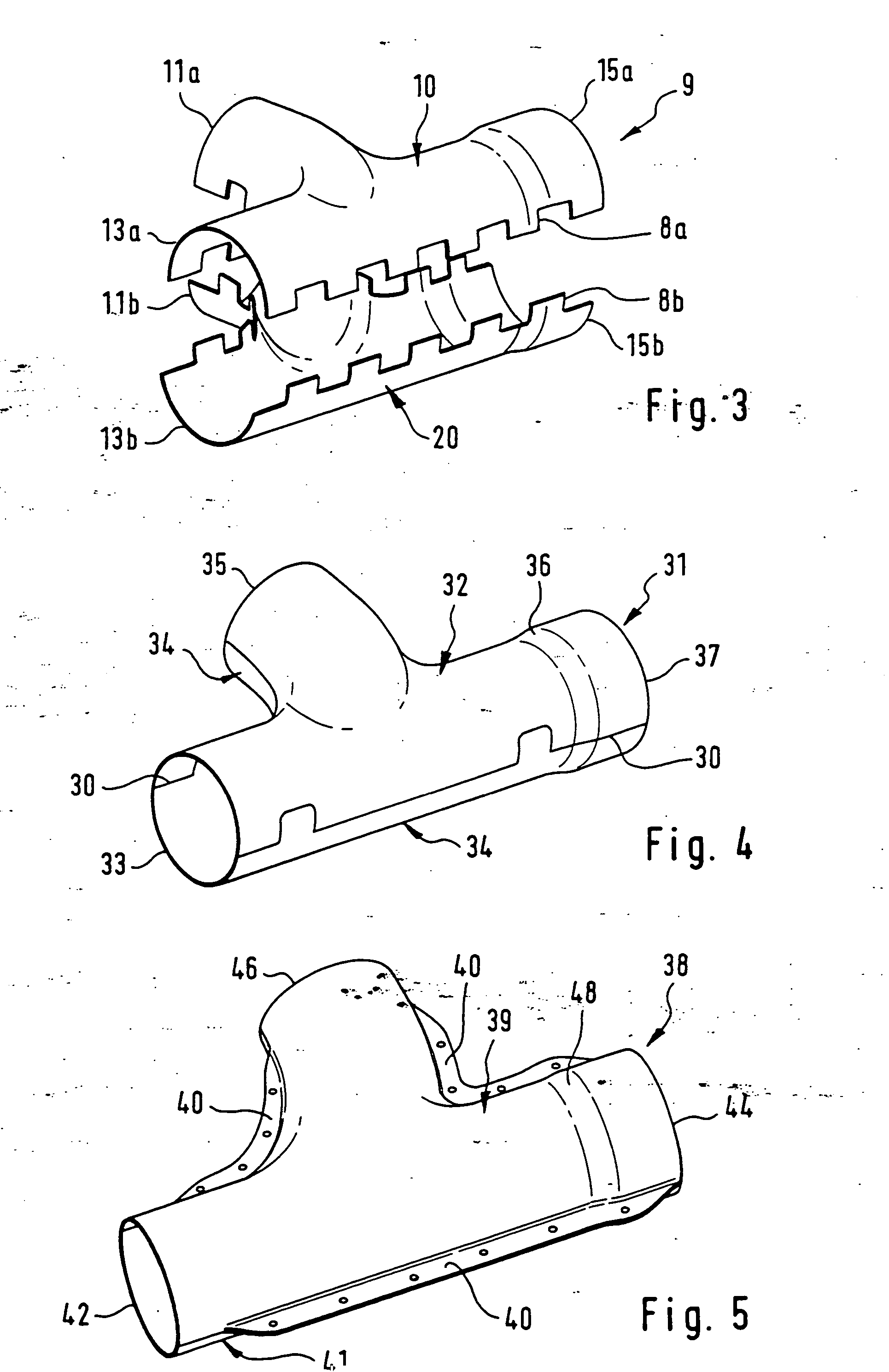
[0030] The figures are described in association with each other and overlapping. The same reference number means the same element.

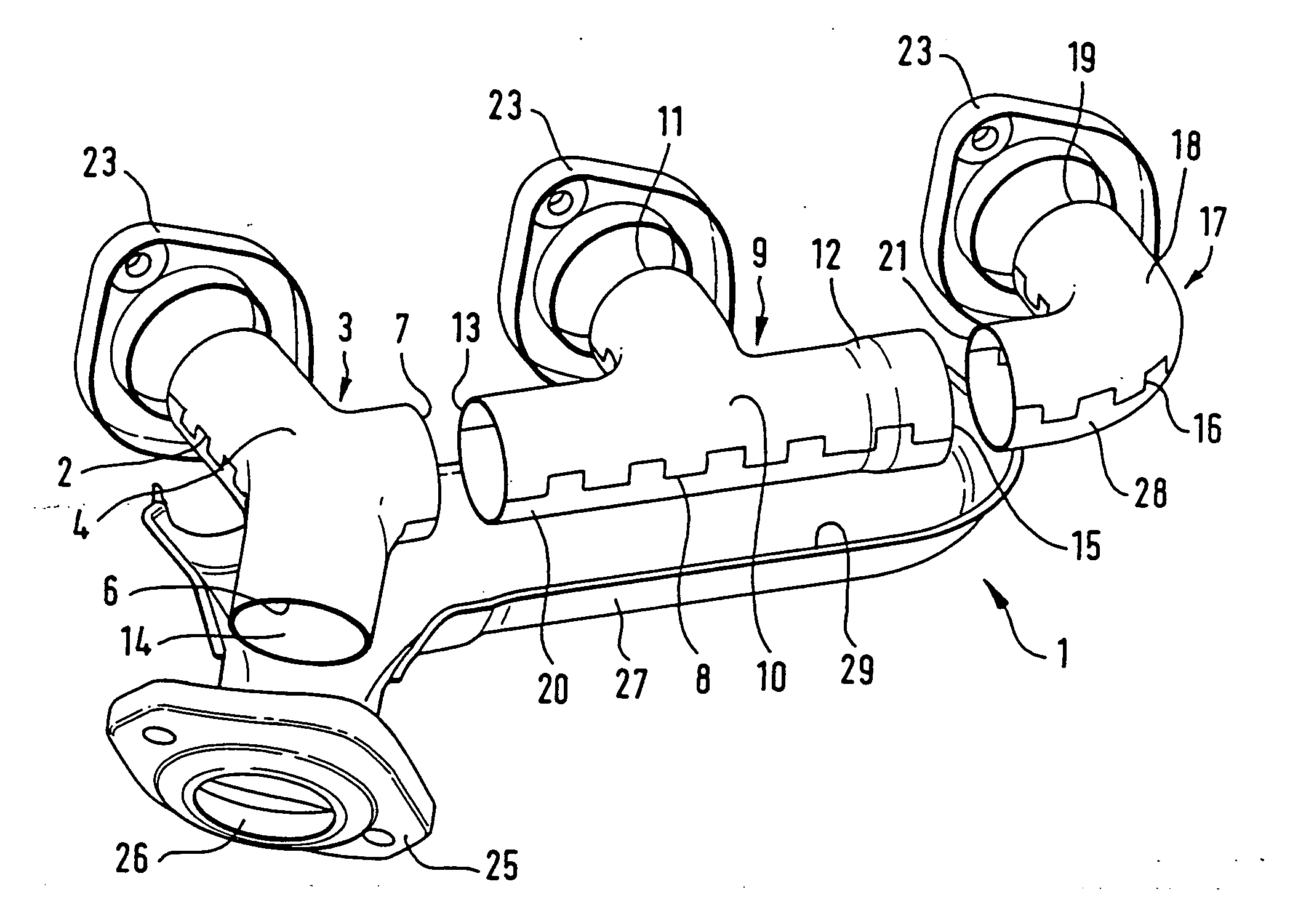
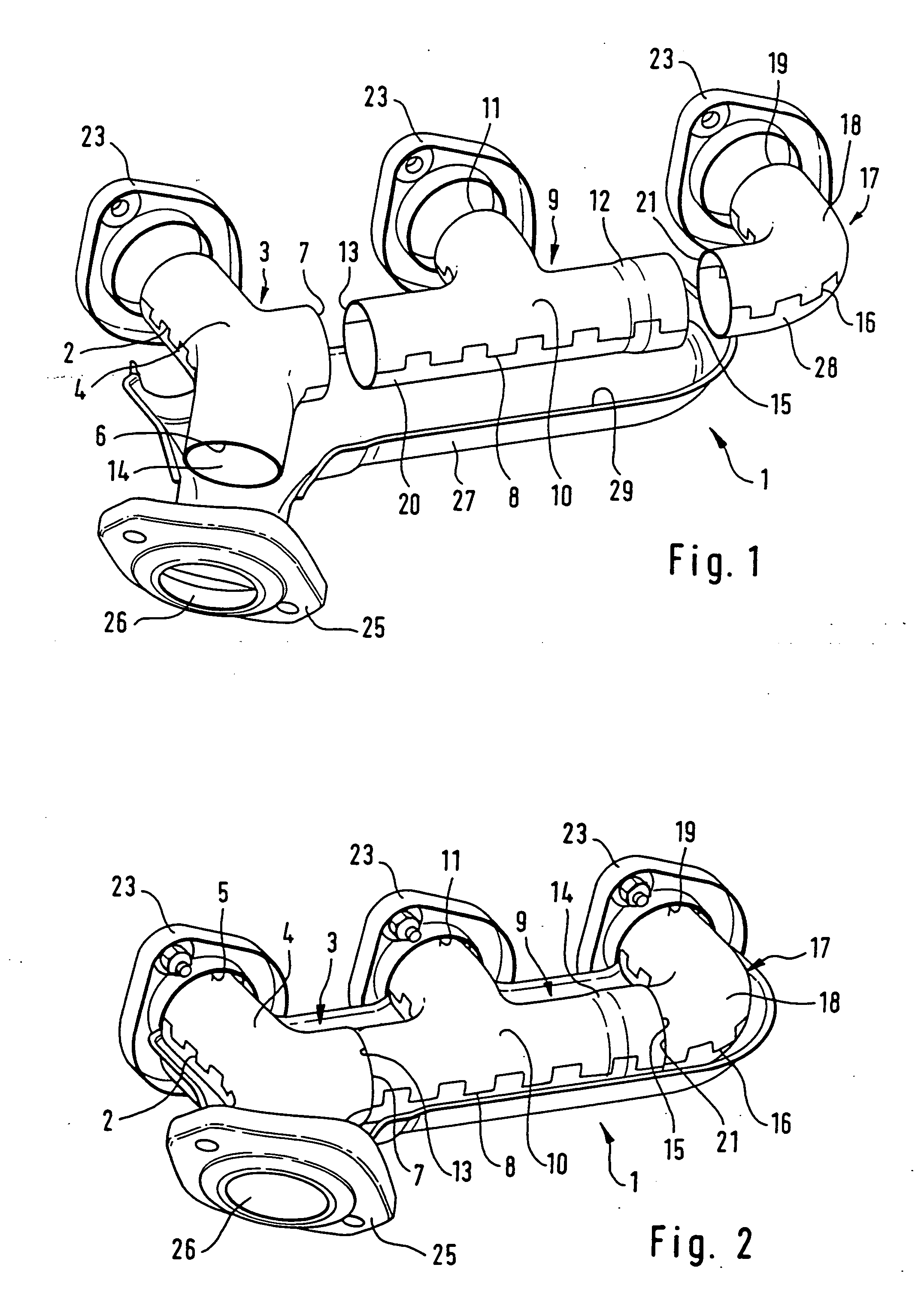
[0031] The exhaust manifold 1 represented schematically in FIG. 1 is comprised of three shell manifolds 3, 9, 17. The first shell manifold 3 exhibits three pipe-like openings, namely, an outlet 6 as well two inlets 5, 7. A first inlet 5 is secured via a flange 23 to a first cylinder of a not shown internal combustion engine, so that the inlet 5 opens directly into this cylinder. A joining or securing of this type can be provided by welding.

[0032] The outlet 6 of the first shell manifold 3 is directed towards an exhaust or a catalytic converter. For compensation of thermal expansion, which occurs as a result of operation of the internal combustion engine, it is provided, that the outlet 6 is provided moveably in an opening 26 of a flange 25, which is secured to an exhaust type or as the case may be a catalytic converter. The first shell manifold 3 is con...


PUM


Abstract

An exhaust manifold for connecting an exhaust pipe with at least one cylinder of an internal combustion engine, and a shell manifold as at least one component of the exhaust manifold. The at least one shell manifold (3, 9, 17, 31, 38) is comprised of at least two shape shells (4, 14, 10, 20, 18, 28, 32, 34, 39). The shape shells are joined to each other by mechanical interlocking. The shell manifold exhibits at least one inlet (5, 11, 19, 35, 46). The shell manifold (3, 9, 17, 31, 38) is so designed, that the at least one inlet (5, 11, 19, 35, 46) communicates with the at least one cylinder.

Description

BACKGROUND OF THE INVENTION [0001] 1. Field of the Invention [0002] The invention concerns an exhaust manifold for connecting an exhaust with at least one cylinder of an internal combustion engine, and a shell manifold as at least one component of the exhaust manifold. [0003] 2. Related Art of the Invention [0004] Exhaust manifolds are used in motor vehicles with internal combustion engines as conduits for removal of exhaust gasses produced during combustion in the cylinders of the internal combustion engine. These exhaust manifolds are, in general, pipe-shaped and can be subdivided or, as the case may be, branched in various manners into pipe segments. [0005] Exhaust manifolds in general have a number of inlets corresponding to the number of cylinders in the internal combustion engine, wherein each of these inlets is connected with a respective cylinder, for example via a flange as connecting piece. In this type of exhaust manifold these inlets, connected with the cylinders of the ...

Claims


Application Information

Patent Timeline
Patent Type & Authority Applications(United States)
IPC IPC(8): F01N13/10F01N13/18
CPCF01N13/10F01N13/1872F01N13/18
Inventor BIEN, WILFRIEDBONNY, PIERREBROWN, MARKUSHULSBERG, THOMASKLUSSMANN, UWEKREUTZIG, NORBERTNUHN, HOLGERPUNJER, RALFREINHARDT, OLAVSTERNAI, THORSTEN
Owner DAIMLER AG
Why Eureka
Try Eureka