
Controls for magnetic stirrer and/or hot plate

a technology of magnetic stirrers and hot plates, which is applied in the direction of hot plate heating arrangements, baking plants, transportation and packaging, etc., can solve the problems of time-consuming and frustrating for users, loss of stirring speed setpoint, and magnetic stirrer clacking around in the vessel, etc., to achieve quick stopping and pause the stirring action.

Inactive Publication Date: 2005-08-25
BARNSTEAD THERMOLYNE
View PDF34 Cites 22 Cited by
  • Summary
  • Abstract
  • Description
  • Claims
  • Application Information

AI Technical Summary

Benefits of technology

"The present invention provides a control for a stirrer or stirring hot plate that allows users to easily pause or interrupt the stirring action without losing the desired speed setpoint. This control allows for quick removal and replacement of vessels without having to reprogram the stirring speed. The control also allows users to select calibration temperatures for different applications. The invention provides a magnetic stirrer with a programmable control that can initiate a pause operation by stopping the spinning action of the stirring bar. The control can also calibrate the temperature measurement system to a calibration temperature. The technical effects of the invention include improved efficiency and flexibility in stirring and heating processes."

Problems solved by technology

However, upon removing power, the stirring speed setpoint is lost and has to be reprogrammed after the power is turned back on.
That abrupt decoupling results in the magnetic stir bar clanging around in the vessel.
Such a process is time consuming and frustrating to a user.
As stirrers, hot plates and stirring hot plates become more versatile with additional programmable features, the control panel or user interface required for programming and operation also becomes more complicated.
Some such devices use LED screens or other displays in combination with a keypad for entering programming functions; however, while displays and keypads are very versatile, they do have some disadvantages.
For example, the entry of data by a user requires navigating through a series of menu screens which can be time consuming and subject to error.
In addition, stirring hot plates are often located on a bench; and the indicia displayed on a screen is not always readily readable by a user.
While more traditional control knobs and switches are easy and quick to use, the addition of new features requires more control knobs and switches; and the physical size of a control panel can become too large.
Commercially available temperature sensors that are used to detect hot plate temperature provide an output signal that changes with temperature, but such changes do not represent an accurate temperature measurement.
The use of several factory preset calibration temperatures is one approach to addressing the temperature control limitations, but it does have a major disadvantage.
It does not allow the user to select a calibration temperature that is specific to a user's particular application.
If the user requires a temperature setpoint that is between the factory preset calibration temperatures, the control may not be able to satisfactorily control the temperature of the hot plate to a desired temperature setpoint.

Method used


Image

  • Controls for magnetic stirrer and/or hot plate
  • Controls for magnetic stirrer and/or hot plate
  • Controls for magnetic stirrer and/or hot plate

Examples


Embodiment Construction

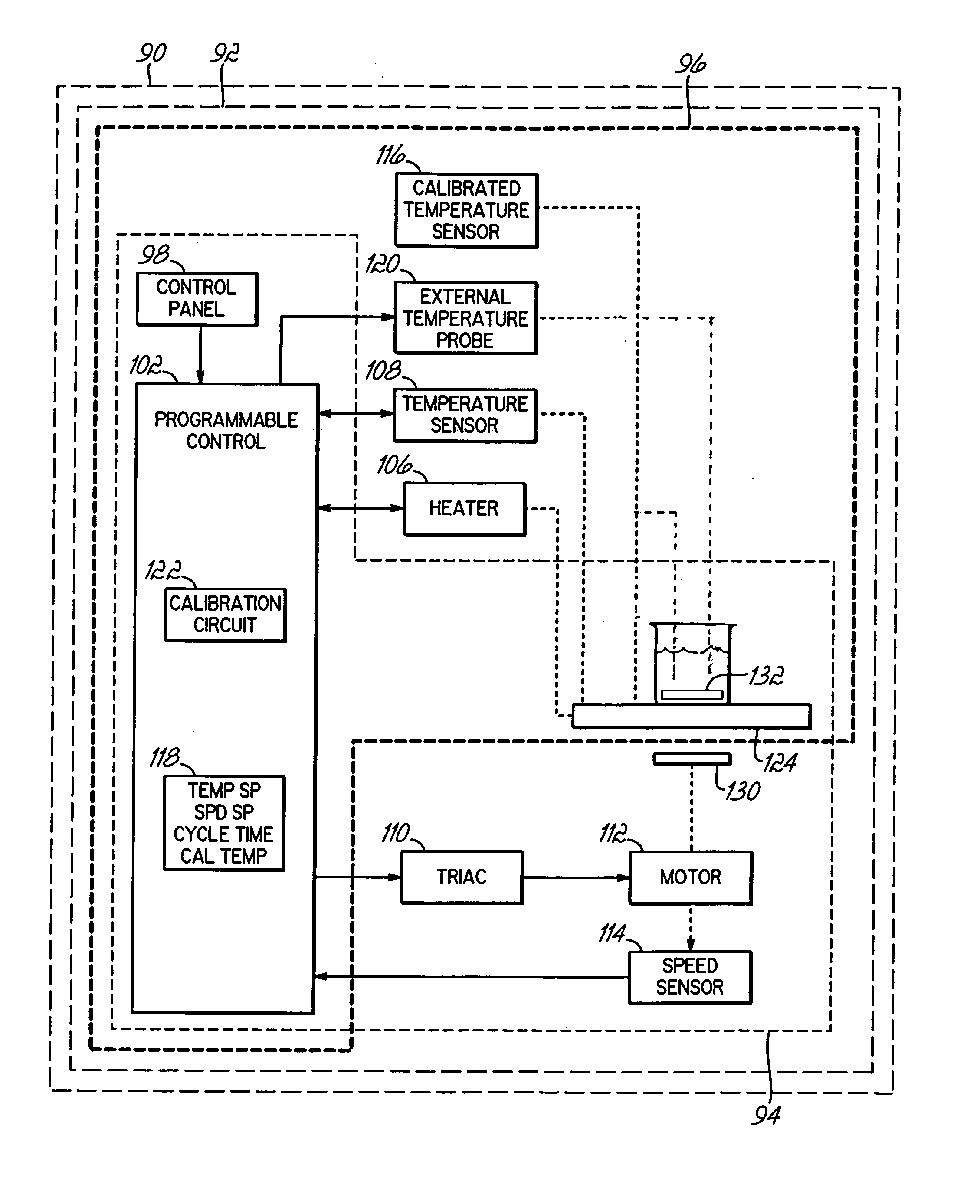
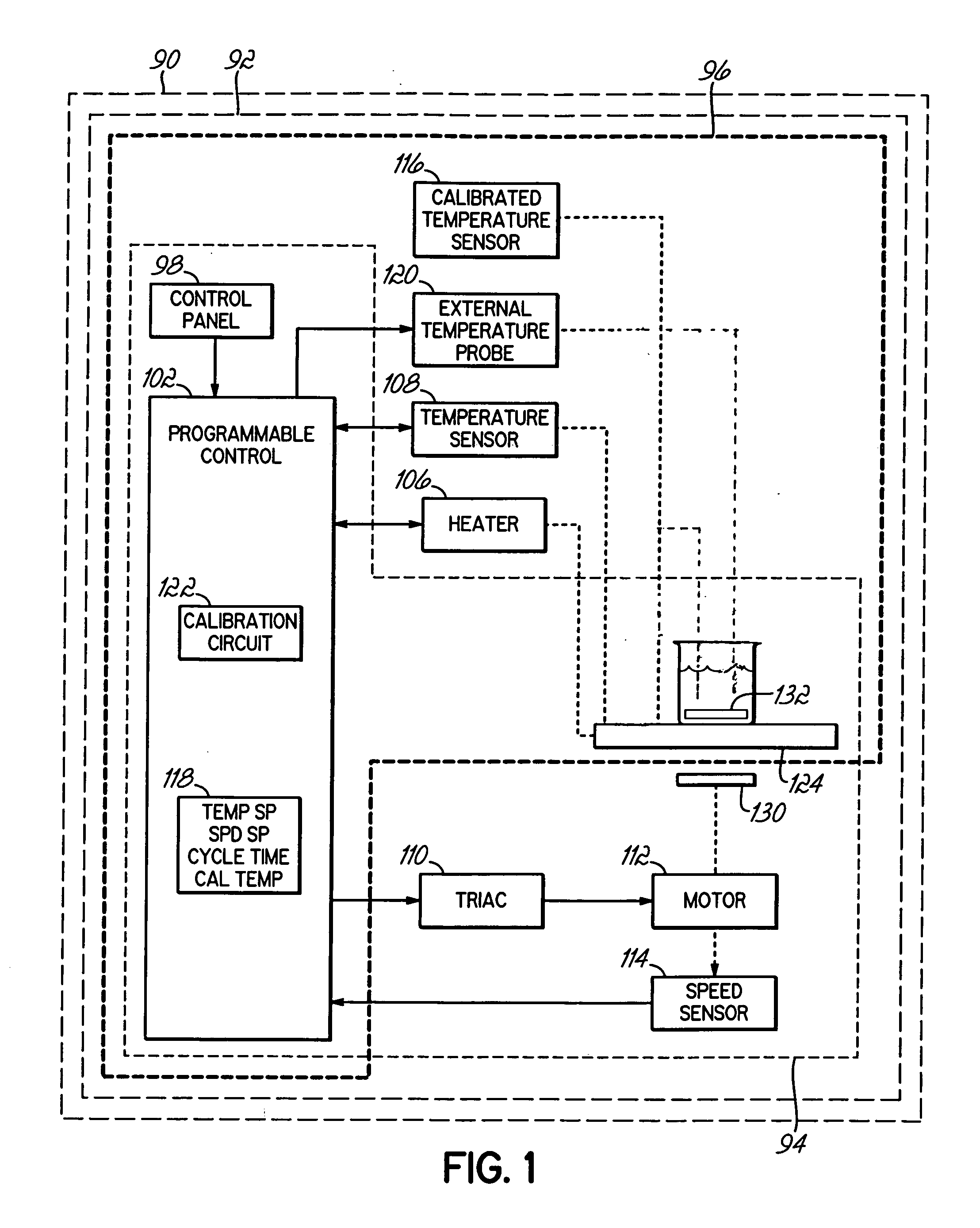
[0026] Referring to FIG. 1, the components illustrated therein are exemplary of either a stirrer, hot plate or stirring hot plate; and as used herein, the term “unit” refers to any one of a stirrer, hot plate of stirring hot plate. Thus, a unit 90 includes either a stirring hot plate 92 that utilizes all of the components shown in FIG. 1, a stirrer 94 that utilizes a control 102, a control panel 98, a triac 110, a motor 112 and speed sensor 114 or a hot plate 96 that utilizes the control 102, control panel 98, the heater 106, temperature sensor 108, calibrated temperature sensor 116, external probe 120 and calibration circuit 122. The various inventions described herein relate, as applicable, to the stirrer 94, the hot plate 96 or the stirring hot plate 92.

[0027] The control 102 can be implemented using one or more known programmable controls, controllers, microcontrollers, etc. that are capable of managing the operation of the unit 90 according to embedded software routines. One o...


PUM


Abstract

Controls for stirrers, hot plates and stirring hot plates provide respective user interfaces having a single control knob that is used to provide a plurality of setpoints. The control permits a user to pause a stirring operation of stirrers and stirring hot plates, unload a vessel, load a new vessel, and restart the stirring without having to re-enter a speed setpoint. Also, current operational parameters may be stored as preset setpoints. The control further permits a user to program a calibration temperature that is similar to the temperatures expected to be encountered during operation.

Description

RELATED APPLICATIONS [0001] The present application is a continuation-in-part of U.S. patent application Ser. No. 10 / 922,438, entitled STIRRING HOT PLATE, filed on Aug. 21, 2004, which claims the benefit of U.S. Provisional Patent Application Ser. No. 60 / 496,744 entitled STIRRING HOT PLATE, filed on Aug. 21, 2003 and the benefit of Ser. No. 60 / 547,377 entitled STIRRING HOT PLATE, filed Feb. 24, 2004, the disclosures of which are herein incorporated by reference in their entirety.FIELD OF THE INVENTION [0002] This invention relates generally to laboratory equipment and more particularly, to controls for, and the operation of, magnetic stirrers, hot plates and stirring hot plates. BACKGROUND OF THE INVENTION [0003] Magnetic stirrers and stirring hot plates are widely used in the chemical, medical, food and agricultural technology industries. With either device, a stirring operation is obtained by using a stationary base with a platform or plate on which a fluid vessel rests. A magneti...

Claims


Application Information

Patent Timeline
Patent Type & Authority Applications(United States)
IPC IPC(8): H05B3/68
CPCB01F13/0006B01F15/00168B01F15/00175H05B3/68B01F15/00389B01F15/00396B01F15/00363B01F33/053B01F33/452B01F35/2114B01F35/2115B01F35/2214B01F35/221422B01F35/2215B01F35/92
Inventor MCFADDEN, CURTHERMSEN, KENNETH DAVIDEARLE, ROGER W.EDWARDS, JAMES R.LEPPERT, KERRY W.JACKSON, ERICGARZ, ERICLOCKWOOD, MARK
Owner BARNSTEAD THERMOLYNE
Learn More