Heat sink

a heat sink and heat radiation technology, applied in the field of heat sinks, can solve the problems of affecting the cooling effect affecting and affecting the cooling effect, so as to facilitate thermal diffusion and heat transfer, reduce the thermal resistance of the heat transfer route from the exothermic member to the flat fin, and improve the heat radiation efficiency of the heat sink

Inactive Publication Date: 2005-08-25
THE FUJIKURA CABLE WORKS LTD
View PDF13 Cites 5 Cited by
  • Summary
  • Abstract
  • Description
  • Claims
  • Application Information

AI Technical Summary

Benefits of technology

[0012] According to the invention, therefore, both top and bottom portions of the air passage being defined by the flat fins are opened. In other words, the air passage is opened on the base portion side and the upper side. For this reason, in case of arranging an air blowing means above the base portion and fins and sending cooling air into the air passage, the airflow vertical to the base portion is discharged from the lower end of the air passage. As a result, airflow resistance in the air passage is reduced and the flow of the cooling air is thereby facilitated. This improves the heat radiating characteristics of the heat sink entirely.
[0018] According to the invention, therefore, the heat generated by the exothermic member is transferred to the base portion through the pedestal portion. This facilitates thermal diffusion and heat transfer from the exothermic member to the base portion. Consequently, a thermal resistance of the heat transfer route from the exothermic member to the flat fins is reduced, and the heat radiating characteristics of the heat sink is thereby improved entirely.

Problems solved by technology

However, if the base portion is relatively large compared to the cooling object, i.e., to the exothermic member, the thermal resistance of the base portion is increased so that the heat radiation efficiency (i.e., cooling performance) is degraded.
For this reason, it is difficult for the air flow to get into the clearance between the fins even if the compulsory cooling is carried out.
Furthermore, flow of the cooling air is hindered.
Due to those factors, the heat radiating effect of the heat sink may be deteriorated.
Therefore, the heat radiating performance of the heat sink is limited.

Method used


Image

  • Heat sink
  • Heat sink
  • Heat sink

Examples


Embodiment Construction

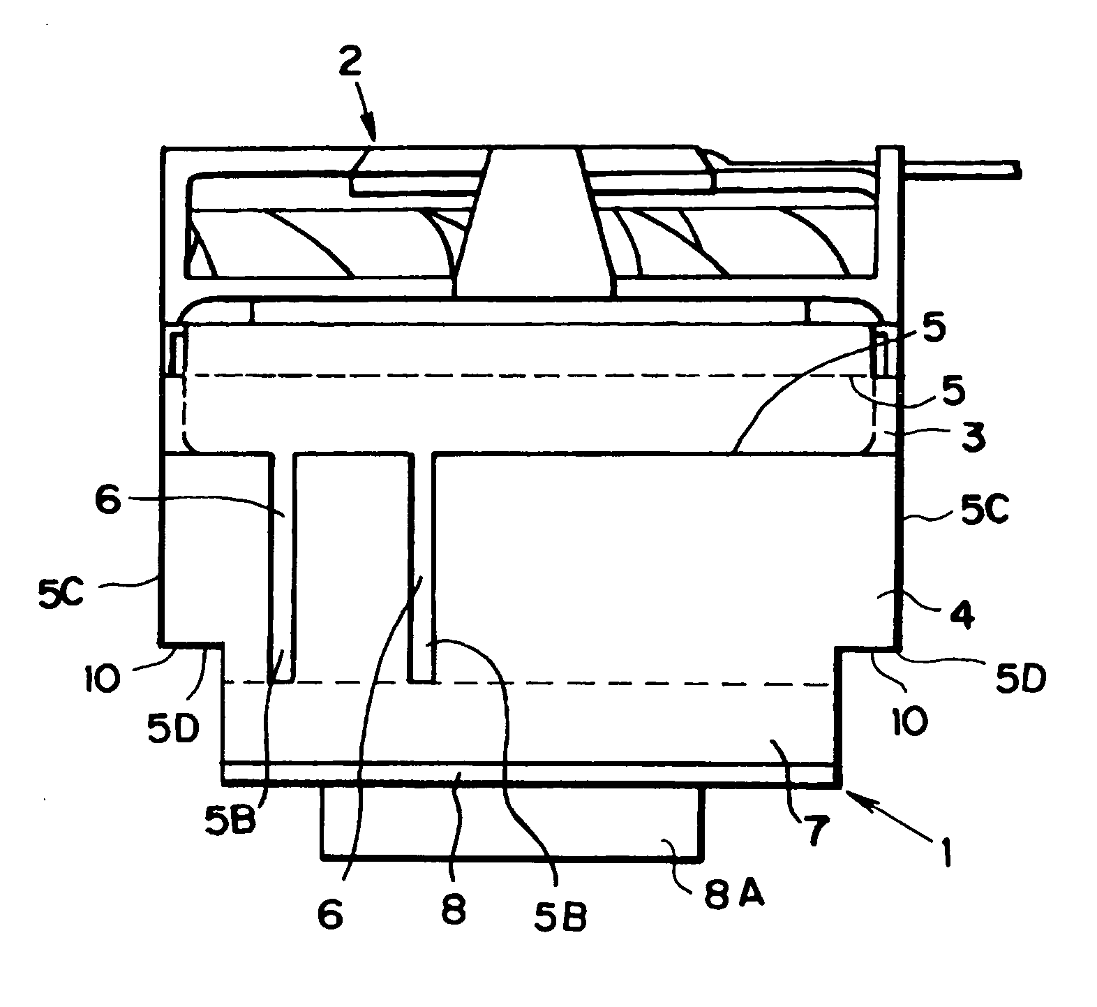
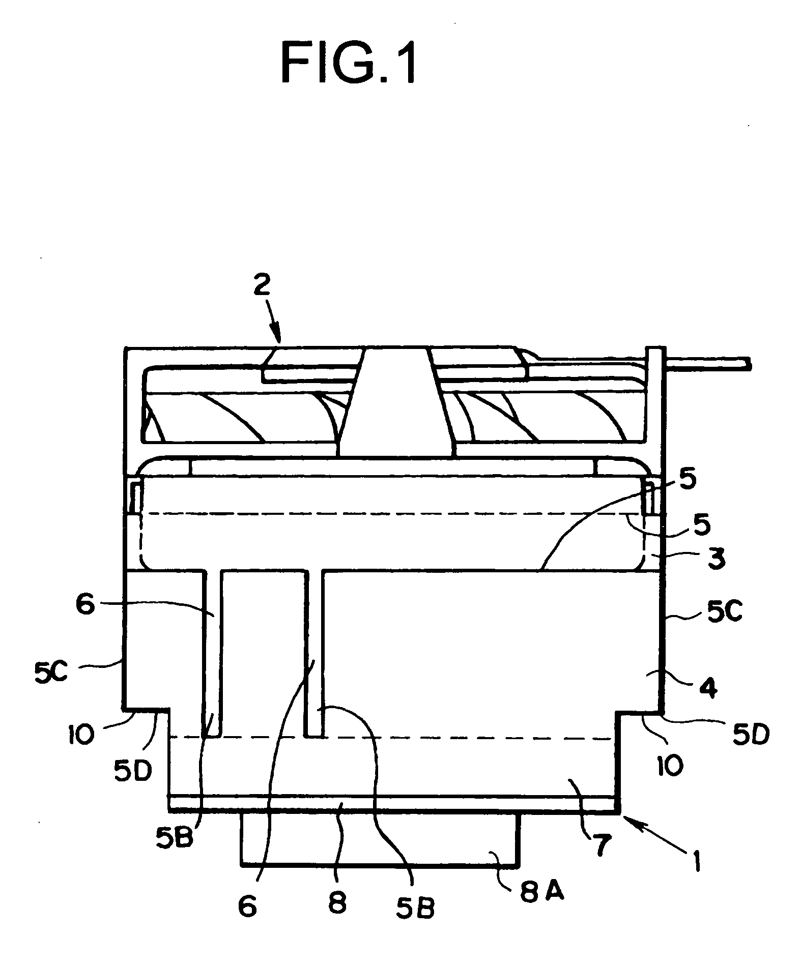
[0026] Here will be described the exemplary embodiment of the invention. FIG. 1 shows one example of a heat sink according to the invention. The construction of the heat sink 1 will be described first of all. The heat sink 1 comprises a flat fin 3, an external wall 4 having a function as a radiation fin, a base portion 7 and a heat spreader 8. The flat fin 3, the external wall 4 and the base portion 7 are formed integrally of aluminum or aluminum alloy, for example. On the other hand, the heat spreader 8 is made of copper.

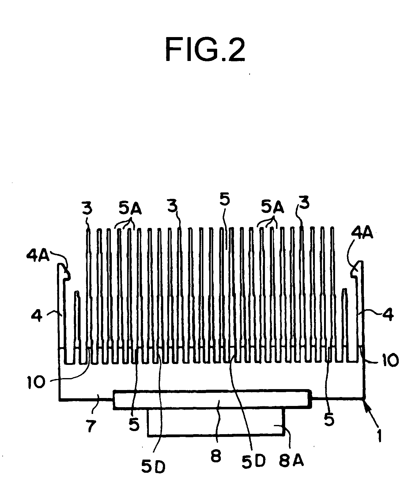
[0027] The flat fin 3 and the external wall 4 are elected on the surface of the base portion 7 at a regular interval in a parallel manner. The longitudinal lengths of the flat fin 3 and the external wall 4 are longer than that of the base portion 7.

[0028] Here will be described the arrangement of the flat fins 3 and the external walls 4. A plurality of the flat fins 3 is arranged at the regular interval in parallel manner on the surface of the base portion 7, and...


PUM


Abstract

A heat sink, which comprises a plurality of flat fins erected on a surface of a base portion, and an air passage defined by the flat fins. In the heat think, at least one of the side end portions of one of the flat fins protrudes outwardly from a peripheral edge of the base portion.

Description

[0001] This application claims priority from Provisional Application Ser. No. 60 / 543,906, filed Feb. 13, 2004, pending, incorporated herein by reference.BACKGROUND OF THE INVENTION [0002] 1. Field of the Invention [0003] The present invention deals with a heat sink comprising a plurality of flat fins erected on a surface of a base portion. [0004] 2. Discussion of the Related Art [0005] Generally, a heat sink is contacted with an exothermic member or a heat source to enlarge the substantial heat radiation area of the exothermic member or the heat source. For this reason, it is preferable to arrange the fins or the heat radiation faces as many as possible in the heat sink of this kind. However, in order to secure the applicability to any kind of cooling objects having various shapes, heat sink having the heat radiation fins on its base portion is used generally. In the prior art, there is known a heat sink, in which flat heat radiation fins are erected integrally on one of a surface o...

Claims


Application Information

Patent Timeline
Patent Type & Authority Applications(United States)
IPC IPC(8): H01L23/467H05K7/20
CPCF28F3/048H01L23/467H01L2924/0002H01L2924/00
Inventor MOCHIZUKI, MASATAKAMASHIKO, KOICHINGUYEN, THANGVISUDTHIMARK, PAKAWATWUTTIJUMNONG, VIJIT
Owner THE FUJIKURA CABLE WORKS LTD
Why Eureka
Try Eureka