
Integrated fire pump controller and automatic transfer switch

Active Publication Date: 2005-08-25
HUBBELL INC
View PDF8 Cites 31 Cited by
  • Summary
  • Abstract
  • Description
  • Claims
  • Application Information

AI Technical Summary

Benefits of technology

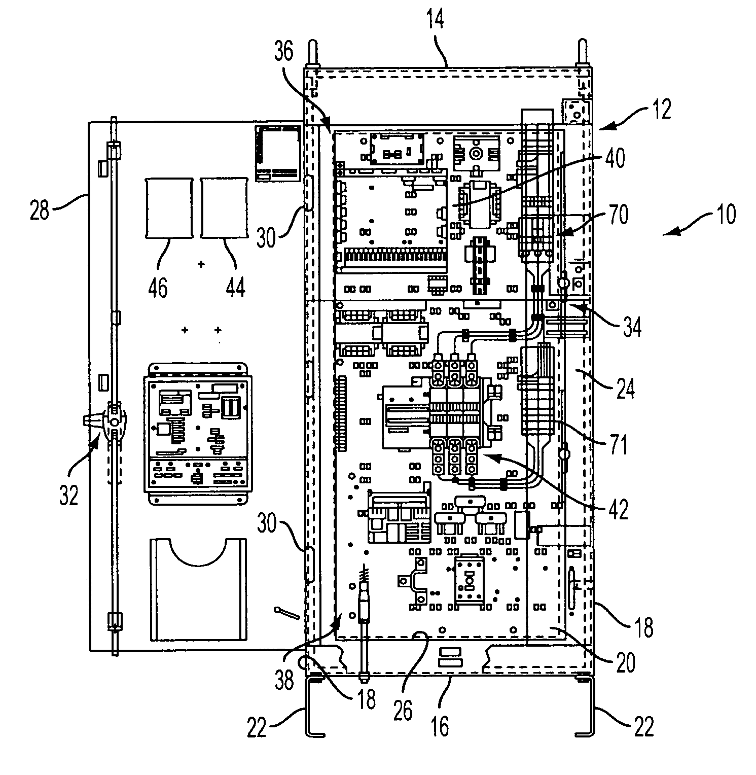
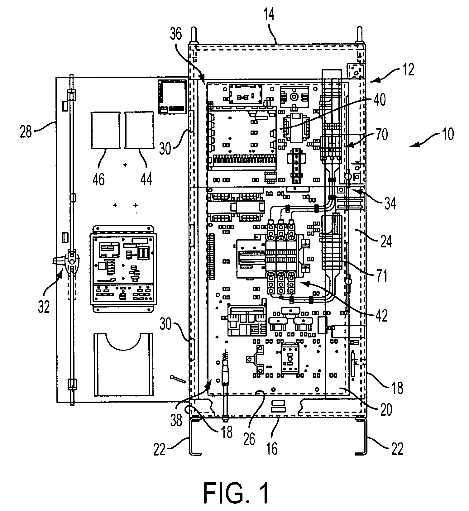
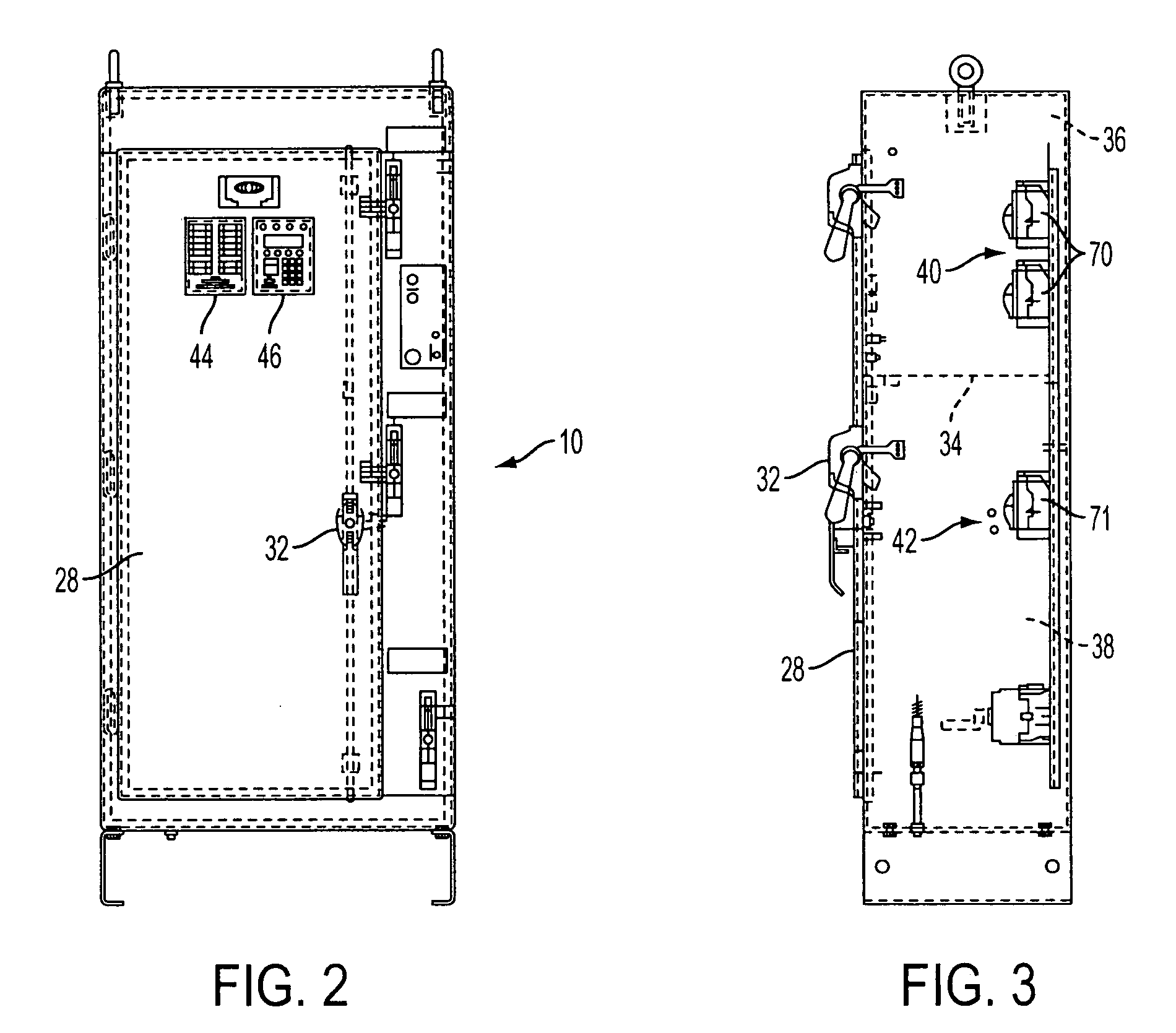
[0012] In one embodiment of the invention, the cabinet includes a first compartment and at least one second compartment separated from the first compartment by an intermediate internal wall. In preferred embodiments, the cabinet and the internal wall are made of steel or other fire resistant material. In one embodiment, the cabinet has a substantially rectangular shape with the internal wall extending between the opposite side walls and contiguous with the rear wall. Preferably, the first and second compartments are stacked in a vertical relationship to reduce the floor space that is required for the assembly. The stacked arrangement provides a unitary assembly that satisfies building code regulations and minimizes space requirements for the assembly.
[0013] The assembly of the present invention eliminates the need for separate cabinets or enclosures, reduces the amount of wiring between the components, and enables the elimination of duplicate components. By providing a single cabinet with an internal wall to define a first compartment for the pump control system and a second compartment for the transfer switch, the space requirements for the assembly is significantly reduced.

Problems solved by technology

These devices typically require large amounts of floor space which increases the difficulty of constructing and assembling such systems and decreases efficient use of limited pump room or utility room floor space.
The electric motors that operate the pumps are generally large and powerful and require large amounts of electrical power.
In particular, these large electrical motors require large amounts of electrical power to start the motors which can cause sudden increases and decreases in the water pressure within the water pipes of the system.
These sudden changes in water pressure, and particularly a sudden increase in water pressure, can cause damage to the valves, pumps, pressure regulators and other equipment.
These prior devices, with their separate transfer switching enclosures, are mounted side-by-side, and thus, require a significant amount of floor space.
These devices have been generally effective for their intended purpose but have not overcome all of the limitations and deficiencies of the prior systems.

Method used


Image

  • Integrated fire pump controller and automatic transfer switch
  • Integrated fire pump controller and automatic transfer switch
  • Integrated fire pump controller and automatic transfer switch

Examples


Embodiment Construction

[0026] The present invention is directed to a unitary housing for enclosing and supporting the electrical components of a fire pump control system. The invention is further directed to a self-contained fire pump controller and transfer switch assembly 10, as shown in FIG. 1. The fire pump controller and transfer switch assembly 10 is preferably provided in a pump room or utility area of a building, for example, where the pump for controlling the supply of water to the fire suppression system for the building is located, as well as a secondary energy source such as a secondary utility line or generator. The fire pump controller and transfer switch assembly 10 of the present invention is advantageous over conventional fire pump controller and power transfer systems because it employs a unitary cabinet that has a smaller footprint, and therefore requires less floor space. As described in further detail below, the fire pump controller and transfer switch assembly 10 is also configured t...


PUM


Abstract

A unitary fire pump controller and transfer switch assembly is housed in a single cabinet having a fire resistant barrier dividing the cabinet into at least two separate compartments. A fire pump controller device is contained within a first compartment. An automatic transfer switch is contained in the second compartment and separated from the control device by the barrier.

Description

[0001] This application claims the benefit of U.S. Provisional Patent Application No. 60 / 539,987 filed Jan. 30, 2004, which is hereby incorporated by reference in its entirety.FIELD OF THE INVENTION [0002] The present invention is directed to a fire controller and transfer switch assembly. The invention is particularly directed to a fire pump controller and automatic transfer switch that is assembled in a single cabinet having a reduced form factor. BACKGROUND OF THE INVENTION [0003] Fire pump control systems are commonly used in large buildings to control the flow of water to sprinkler heads as part of a fire suppression system. A fire pump control system operates a pump system for directing high pressure water to the sprinkler heads.[0004] The pump control system is connected to various fire detectors and sensors and activates a pump in the event of a fire to supply the water to the desired location. The control system typically controls the water pressure, flow rate, starting of ...

Claims


Application Information

Patent Timeline
IPC IPC(8): A62C25/00A62C27/00A62C29/00A62C35/00A62C37/44
CPCA62C37/44
Inventor TAYLOR, ZANE A.FLYER, MATTHEW T.MILLER, CRAIG I.HAPEMAN, LAWRENCE M.
Owner HUBBELL INC
Learn More