
Dynamically determining directions of freedom for control points used to represent graphical objects

a control point and freedom technology, applied in the direction of instruments, computing, drawing from basic elements, etc., can solve the problems of consuming significant computing system resources, storing characters as bitmaps (either fixed or proportional), and a large number of bitmaps by hand is extremely time-consuming, so as to reduce the likelihood of causing

Inactive Publication Date: 2005-08-25
MICROSOFT TECH LICENSING LLC
View PDF55 Cites 9 Cited by
  • Summary
  • Abstract
  • Description
  • Claims
  • Application Information

AI Technical Summary

Benefits of technology

The present invention is about a system and method for determining the directions of freedom for control points used to represent graphical objects such as text. The system calculates the likelihood of non-compliance with other constraints and automatically determines a direction of freedom for the control point to reduce the likelihood of non-compliance. The technical effect of the invention is to improve the efficiency and accuracy of control points in computer graphics applications.

Problems solved by technology

However, storing characters as bit-maps (either fixed or proportional) can still consume significant computing system resources.
The storage requirement problems associated with bit-map fonts is further compounded when a computing device is to display and print characters from different fonts.
Further, producing a large number of bitmaps by hand is extremely time consuming.
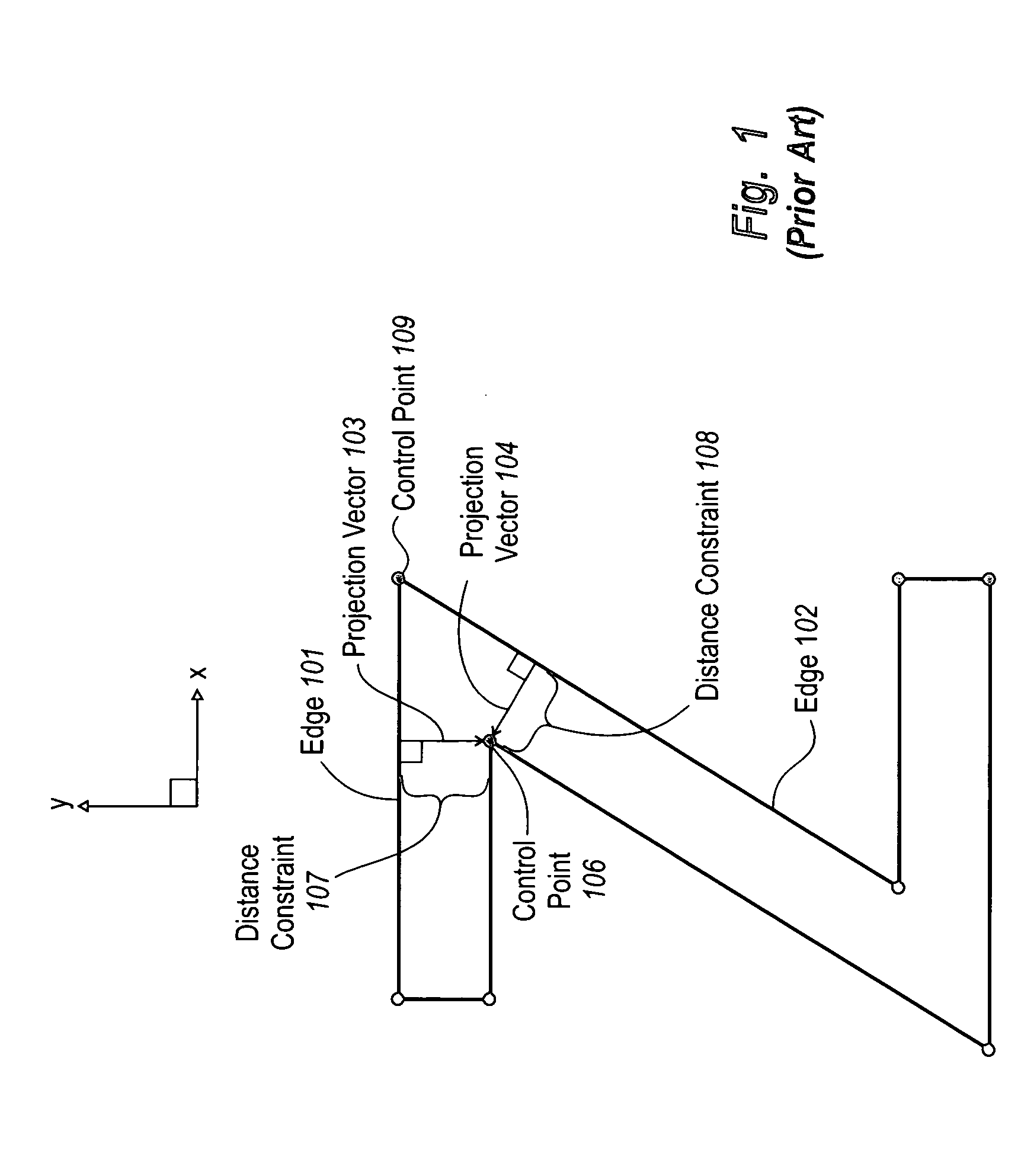
Accordingly, inappropriate selection of freedom vectors can result in the inability to comply with constraints.
Further complications can arise when a control point is to comply with a plurality of constraints.
Failure to set the freedom vector corresponding to the second applied constraint perpendicular to the projection vector corresponding to the first applied constraint can result in compliance with the first applied constraint being undone.
Further, movement along diagonal freedom vectors can result in numerical errors (e.g., due to rounding) in the rendering process.
However, manual hinting can consume a considerable amount of time.
For example, it may take weeks or even months for a trained typographer to hint a single font.
Automated hinting, as performed by a computing system, is difficult to implement since a computing system has no inherent understanding of freedom vectors or how to select freedom vectors that increase the likelihood of complying with constraints.
For example, given a set of control points representing a character, a computing system may have no way to determine an appropriate order for applying multiple constraints to a control point.
Thus, a computing system may generate freedom vectors that cause compliance with a previously applied constraint to be undone or may generate freedom vectors with a higher likelihood of causing numerical errors (e.g., diagonal freedom vectors).

Method used


Image

  • Dynamically determining directions of freedom for control points used to represent graphical objects
  • Dynamically determining directions of freedom for control points used to represent graphical objects
  • Dynamically determining directions of freedom for control points used to represent graphical objects

Examples


Embodiment Construction

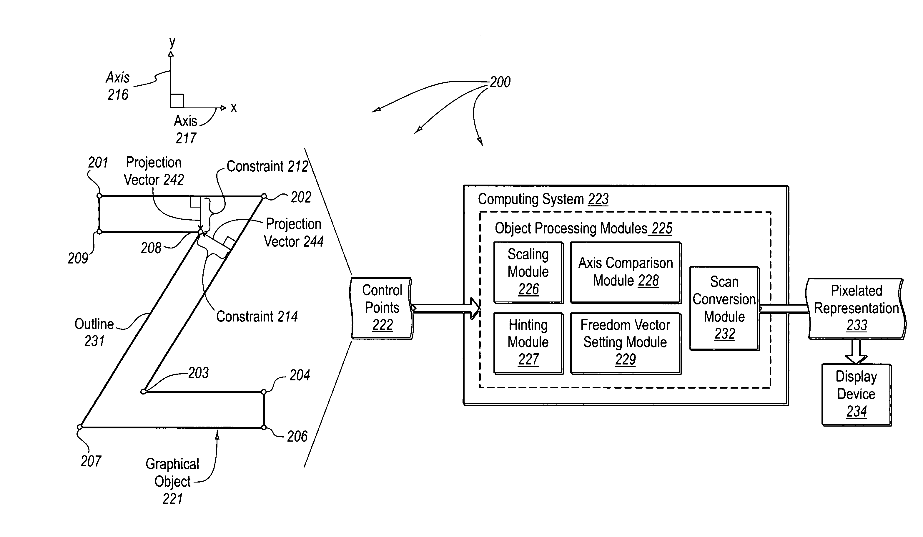
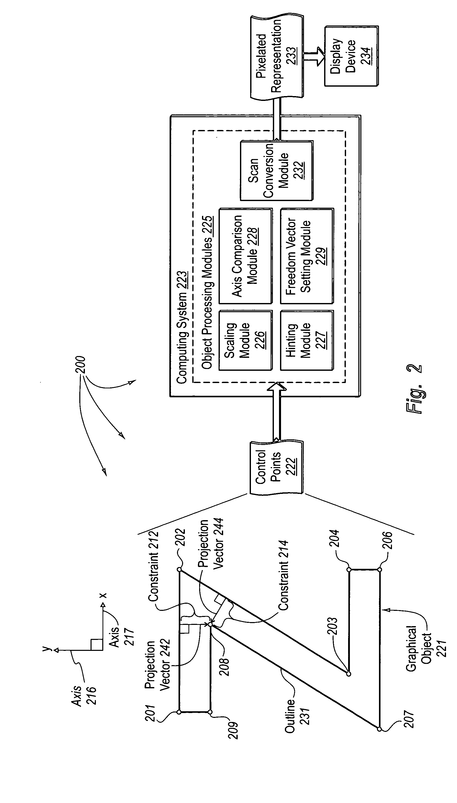
[0032] The principles of the present invention relate to systems, methods, and computer program products for dynamically determining directions of freedom for control points used to represent graphical objects such as text. A computer system receives a set control points (e.g., containing control point locations and computer-executable instructions defining constraints on the control points). The computer system identifies a first projection vector corresponding to a first constraint for a control point (e.g., from contained computer-executable instructions). The computer system determines which of two perpendicular axes (e.g., an X axis and Y axis that is perpendicular to the X axis) is closer to the first projection vector. The computer system sets the direction of a first freedom vector (indicating a direction the control point can move to comply with the first constraint) in the direction of the closer axis.

[0033] When the control point is to comply with a plurality of constrai...


PUM


Abstract

The principles of the present invention relate to dynamically determining directions of freedom for control points used to represent graphical objects such as text. A computing system identifies a first function that represents a first constraint, solutions to the first function indicating compliance with the first constraint. The computing system calculates, based on the location of a control point and the identified first function, that the control point does not comply with the first constraint. The computing system automatically determines a first direction of freedom in which the control point can be moved to comply with the first constraint such that movement of the control point in the first direction of freedom has a reduced likelihood of causing non-compliance with other constraints.

Description

BACKGROUND OF THE INVENTION [0001] 1. The Field of the Invention [0002] The present invention relates to manipulating control data used to generate outlines of graphical objects. More specifically, the present invention relates to dynamically determining directions of freedom for control points used to represent graphical objects such as text. [0003] 2. Background and Related Art [0004] Computing technology has transformed the way we work and play. Computing systems now take a wide variety of forms including desktop computers, laptop computers, tablet PCs, Personal Digital Assistants (PDAs), and the like. Even household devices (such as refrigerators, ovens, sewing machines, security systems, and the like) have varying levels of processing capability and thus may be considered computing systems. As time moves forward, processing capability may be incorporated into a number of devices that traditionally did not have processing capability. Accordingly, the diversity of computing syste...

Claims


Application Information

Patent Timeline
Patent Type & Authority Applications(United States)
IPC IPC(8): G06T11/00G06T11/20
CPCG06T11/203
Inventor STAMM, BEATHITCHCOCK, GREGORY C.DUGGAN, MICHAEL J.
Owner MICROSOFT TECH LICENSING LLC
Learn More