Extrusion auger with removable auger segments and removal tool

a technology of augers and auger segments, which is applied in the field of extrusion augers, can solve the problems of flight wear, damaged or worn flight, and may require replacement or refurbishment, and achieve the effect of sufficient structural strength and convenient safe removal of auger segments

Inactive Publication Date: 2005-08-25
J C STEELE & SONS
View PDF28 Cites 2 Cited by
  • Summary
  • Abstract
  • Description
  • Claims
  • Application Information

AI Technical Summary

Benefits of technology

[0011] The extrusion auger and pulling tool of the present invention may be manufactured in a cost-effective manner with relative ease. The recess of the auger segment provides a convenient surface for gripping the auger segment with the pulling tool, wherein the surface has sufficient structural strength to allow removal without damage to the auger segment. The pulling tool may be conveniently used to exert the pulling forces necessary to overcome the resistance created by the process material, rust, and other impediments. Therefore, the extrusion auger and pulling tool of the present invention provide for convenient safe removal of auger segments.

Problems solved by technology

In some industries, such as the brick industry, constituents of the process materials are very hard and / or abrasive such that the flight is worn during extensive use.
Damaged or worn flights may require replacement or refurbishment for efficient operation of the auger.
Removal of the auger segments is often complicated by the process materials that pass between the auger segments during operation or by rust on the auger shaft and auger segments.
The auger segments are removed axially and such debris and rust can complicate the removal of an auger segment by requiring additional force to overcome the debris, rust, or other impediments.
In addition, some extruders provide limited access to the auger without major disassembly of the extruder.
Gripping the flight portion results in asymmetric application of the removal forces, which increases the forces required to remove the auger segment.
Since the worn flight surfaces are polished and curved they are hard to grip thus increasing the risk of injury to the maintenance personnel.

Method used


Image

  • Extrusion auger with removable auger segments and removal tool
  • Extrusion auger with removable auger segments and removal tool
  • Extrusion auger with removable auger segments and removal tool

Examples


Embodiment Construction

[0019] The present invention now will be described more fully hereinafter with reference to the accompanying drawings, in which some, but not all embodiments of the invention are shown. Indeed, the invention may be embodied in many different forms and should not be construed as limited to the embodiments set forth herein; rather, these embodiments are provided so that this disclosure will satisfy applicable legal requirements. Like numbers refer to like elements throughout.

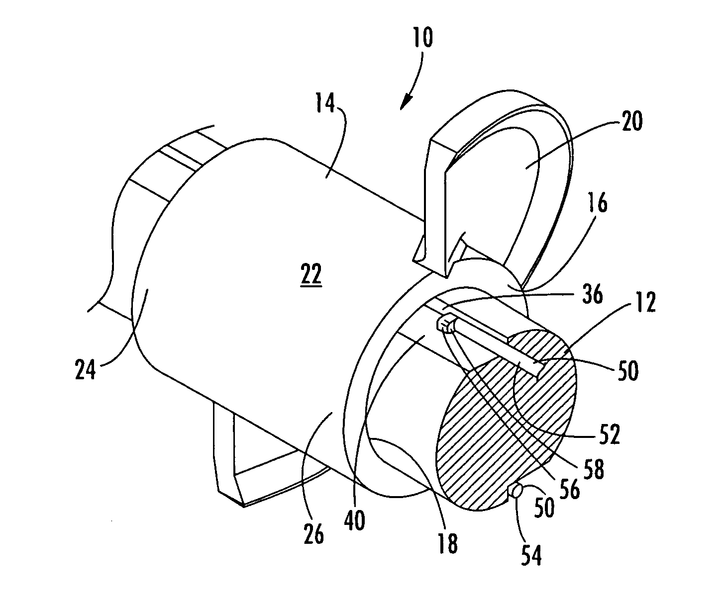
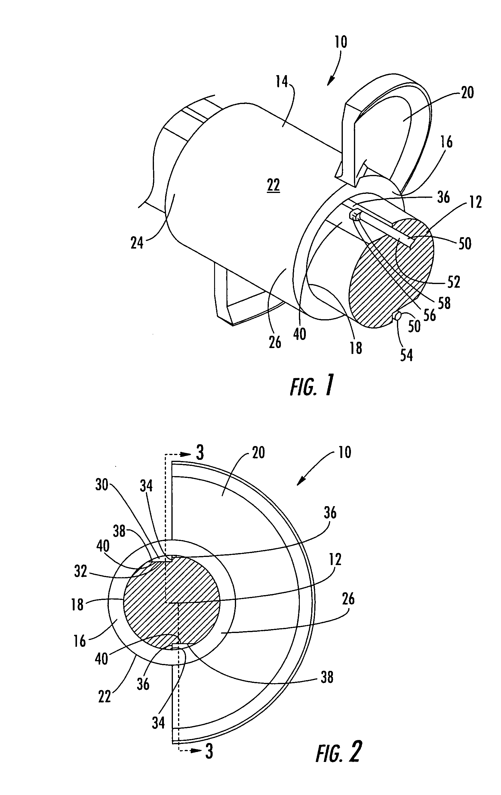
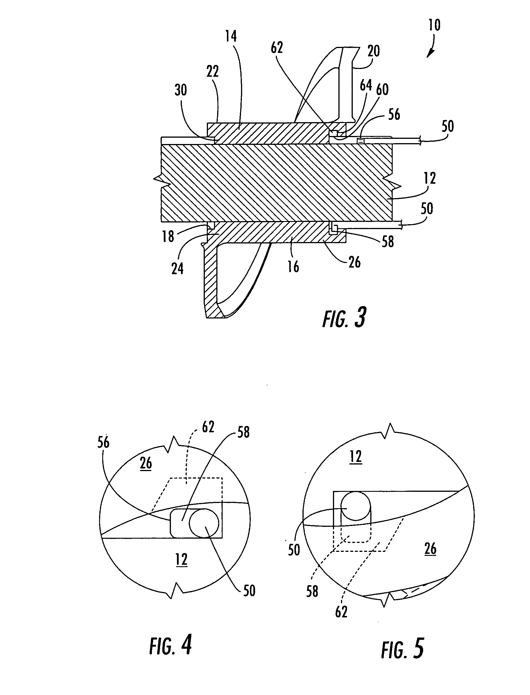
[0020] With reference to FIGS. 1-6, an extrusion auger 10 in accordance with one embodiment of the present invention is illustrated. The extrusion auger 10 includes an auger shaft 12 about which one or more auger segments are removably attached. An auger segment 14 has an auger hub 16 that includes an auger bore 18 that engages the auger shaft 12. At least a portion of a flight 20 is joined to the outer surface 22 of the auger hub 16. The one or more auger segments 14 can be axially attached to the auger shaft 12...


PUM

PropertyMeasurementUnit
hardaaaaaaaaaa
abrasiveaaaaaaaaaa
rotational forceaaaaaaaaaa

Abstract

There is provided an extrusion auger having auger segments that are removable from an auger shaft and that include a recess to facilitate removal of the auger segments. A pulling tool is also provided to engage the recess of the auger segment and to facilitate the removal of auger segment from the auger shaft in an axially forward direction. The auger segment includes an access way to provide access to the recess and the recess includes an engaging surface. The pulling tool includes a flanged end that can pass through the access way of the auger segment and contact the engaging surface of the auger segment. The recess of the auger segment may be located in a bore of the auger hub such that the pulling tool can be advanced along a keyway in the auger shaft, rotated to pass the flanged end of the pulling tool through the access way, and pulled axially forward to contact the engaging surface.

Description

FIELD OF THE INVENTION [0001] The present invention relates generally to extrusion augers. More particularly the invention relates to an extrusion auger having one or more auger segments that are removable from an auger shaft in an axially forward direction. BACKGROUND OF THE INVENTION [0002] Many industries utilize extrusion augers to mix and / or extrude the process materials during the manufacturing of a product. An auger is essentially a shaft having a spiraled flight that rotates to push or pull the process material axially along the auger. The process material is predominately moved by the flight because of the screw-like movement of the flight. In some industries, such as the brick industry, constituents of the process materials are very hard and / or abrasive such that the flight is worn during extensive use. Damaged or worn flights may require replacement or refurbishment for efficient operation of the auger. [0003] Some extrusion augers include removable auger segments that pr...

Claims


Application Information

Patent Timeline
Patent Type & Authority Applications(United States)
IPC IPC(8): B25B27/00B28B3/22B28B13/02B28C5/08B29B7/58B29B7/60B29C31/02B29C48/06B30BB30B9/12B30B11/22B30B11/24B65G33/26E21B10/44
CPCB28B3/222B29C47/0016B29C47/0035Y10T29/49721B29C47/0825B29C47/60B30B11/246B29C47/0818B29C48/06B29C48/131B29C48/256B29C48/2564E21C37/00
Inventor WHITTAKER, CHARLES BURTON JR.BOWLES, JOEY D.
Owner J C STEELE & SONS
Why Eureka
Try Eureka