Wheel axle bearing unit

a technology of bearing unit and axle, which is applied in the direction of bearing unit rigid support, mechanical equipment, transportation and packaging, etc., can solve the problems of inability to design work, too complicated inability to easily carry out examination and solution making, etc., to achieve easy operation, low cost, and increase the capacity of grease deposi

Active Publication Date: 2005-08-25
NTN CORP
View PDF3 Cites 13 Cited by
  • Summary
  • Abstract
  • Description
  • Claims
  • Application Information

AI Technical Summary

Benefits of technology

[0014] The present invention can be easily achieved at a low cost just by forming the groove at the same time as forming the outer circumferential surface of the inner member or the inner circumferential surface of the outer member, and besides the unit can be made lighter in weight by removing an excess in thickness.
[0015] Simply by forming the grooved portion on the outer member and the inner member, a space inside the bearing is enlarged by an amount equivalent to the grooved portion, and a grease deposit capacity is increased. Accordingly, such structure prevents overheating caused by intrusion of a large amount of grease into between the rolling elements due to vibration propagated to the bearing, and grease leakage because of softening or oil separation of a thickening agent due to mechanical shearing effect by the rolling elements.

Problems solved by technology

However, it has proved that in a system where the inner race rotates a centrifugal force is not applied to the outer member, and that hence such design is not workable.
Consequently, in the case where a large amount of grease accidentally flows into between the rolling elements 15, there may be caused overheating because of fluid friction of the grease itself, or softening or oil separation due to breakdown of fiber structure of a thickening agent (for retaining an oily substance) in the event that the thickening agent has a low mechanical shear stability, which may even lead to grease leakage.
However, since such measures are related with a life span of the bearing, the examination and solution-making are too complicated to readily carry out.

Method used


Image

  • Wheel axle bearing unit
  • Wheel axle bearing unit
  • Wheel axle bearing unit

Examples


Embodiment Construction

[0030] Hereunder, an embodiment of the present invention will be described referring to the accompanying drawings.

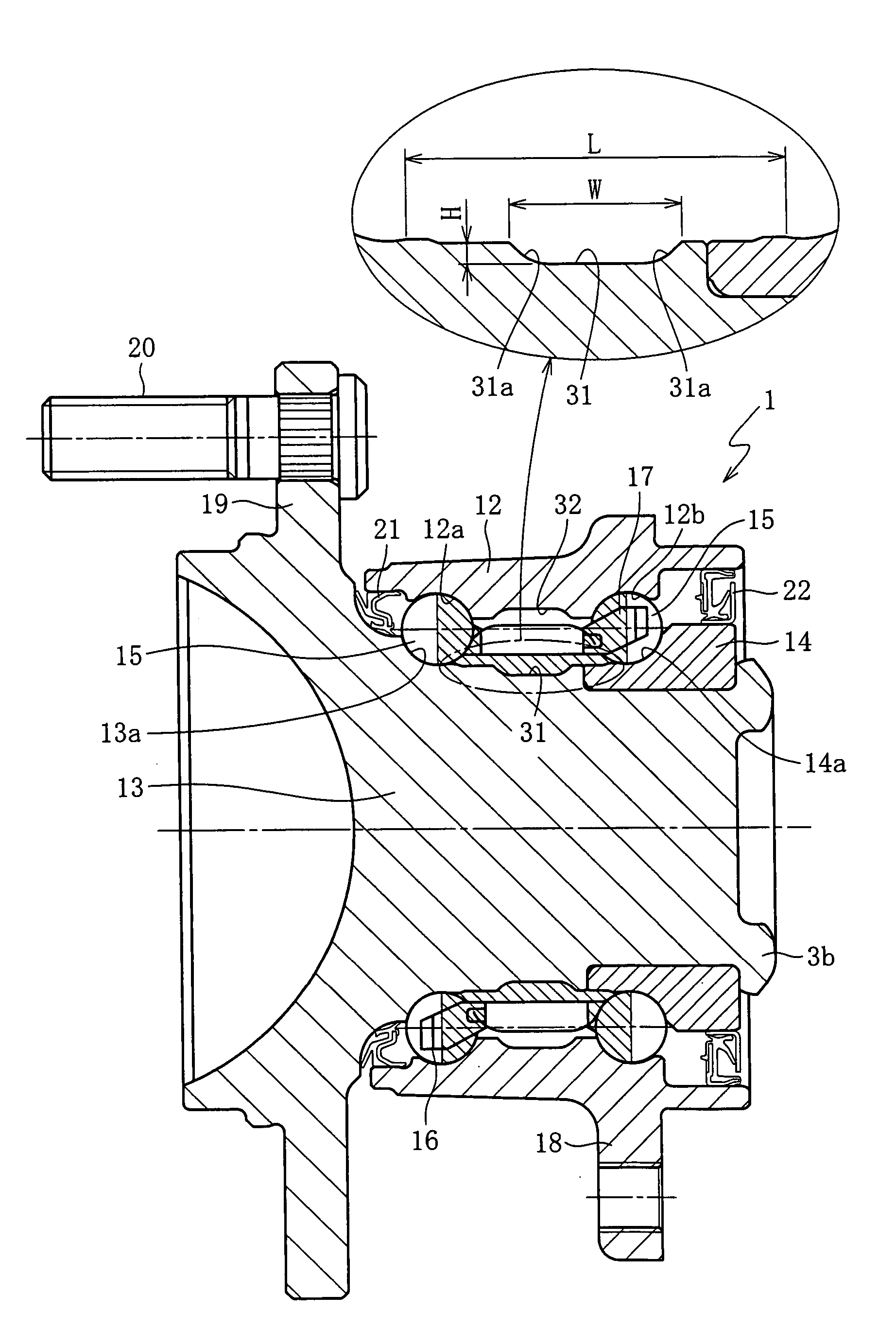
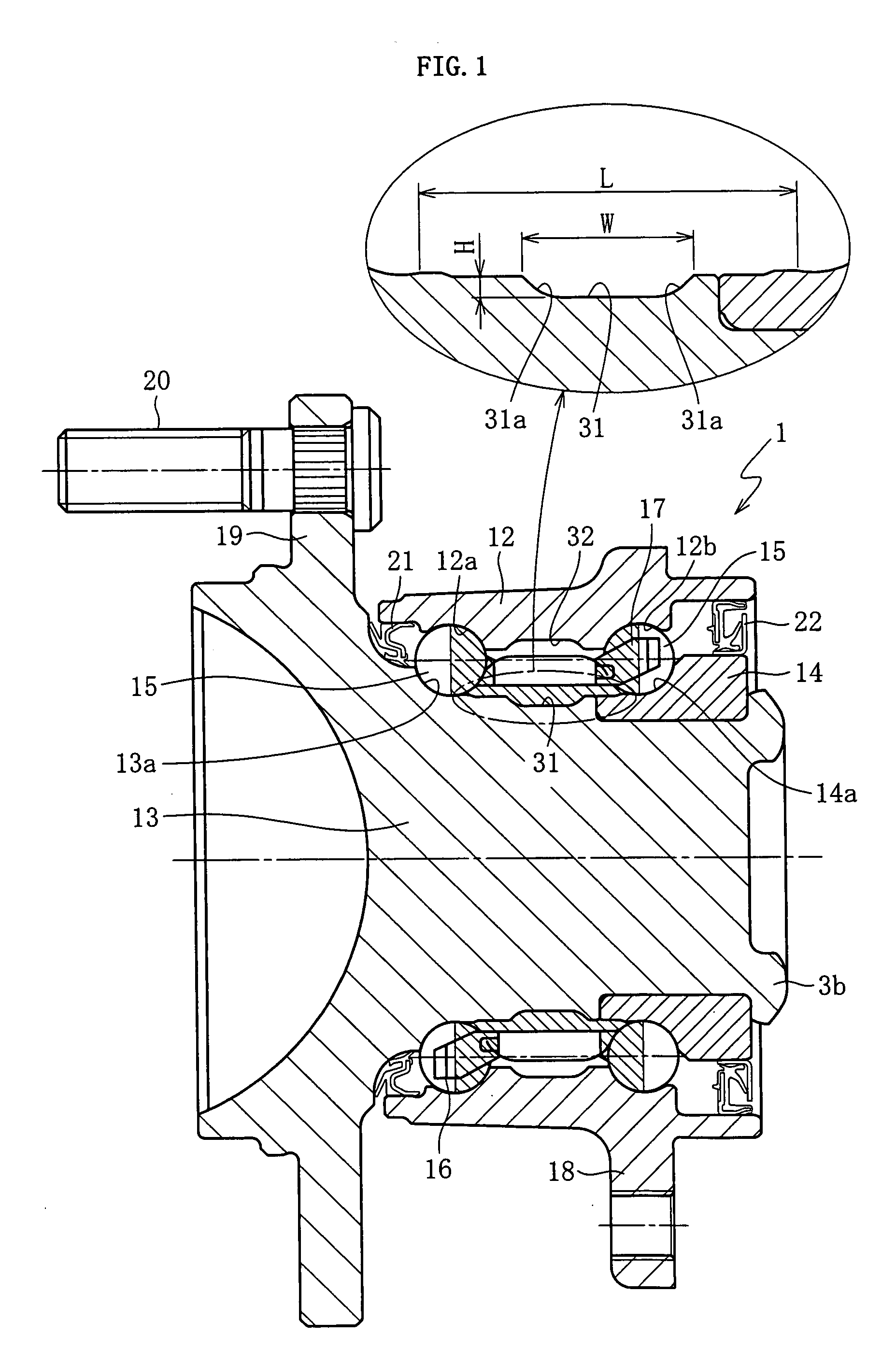
[0031]FIG. 1 shows a bearing unit 1 for a wheel axle sustaining a non-driven wheel (a third generation wheel axle bearing unit) according to the embodiment of the present invention. As shown therein, the bearing unit 1 of the present invention is provided with a first grooved portion 32 formed on an outer circumferential surface of a hub 13 in a region adjacent to an inner edge of an outer-side inner raceway 13a of the hub 13, which is an inner member. The first grooved portion 32 may be formed not only on an outer circumferential surface of the hub 13 but also partly on an outer circumferential surface of the inner race 14.

[0032] A second grooved portion 31 is provided on an inner circumferential surface in a region between inner-side and outer-side outer raceways 12a, 12b of an outer race 12, which is an outer member. The first grooved portion 32 and the second groov...


PUM


Abstract

A wheel axle bearing unit for a vehicle is to be made lighter in weight, so as to prolong a life span thereof. A first grooved portion is formed by removing an excess in thickness in a region between dual raceways on an outer circumferential surface of a hub and an inner race which constitute the inner member of the wheel axle bearing unit, for enlarging a space inside the bearing, thereby increasing an amount of grease that can be retained in the region between the dual raceways. Also at a position corresponding to the first grooved portion, a second grooved portion is formed by removing an excess in thickness on an inner circumferential surface of an outer race, which constitutes an outer member.

Description

BACKGROUND OF THE INVENTION [0001] 1. Field of the Invention [0002] The present invention relates to a wheel axle bearing unit, and more particularly to a bearing unit that has an enlarged space inside the bearing, for preventing overheating and leakage of grease, as well as for making the unit lighter in weight. [0003] 2. Description of the Related Art [0004]FIG. 3 shows a conventional wheel axle (non-driven) bearing unit 11. The bearing unit 11 is called a third generation bearing unit, which includes an outer race 12 constituting an outer member, provided with dual raceways namely outer raceways 12a, 12b along an inner circumferential surface thereof, a hub 13 provided with an outer-side inner raceway 13a along an outer circumferential surface thereof, an inner race 14 provided with an inner-side inner raceway 14a along an outer circumferential surface thereof and fitted to an outer circumferential surface of the hub, spherical rolling elements 15 aligned in dual rows between the...

Claims


Application Information

Patent Timeline
Patent Type & Authority Applications(United States)
IPC IPC(8): B60B27/00F16C19/18F16C33/58F16C33/60F16C33/62F16C33/64F16C33/66
CPCB60B27/00B60B27/0005B60B27/0026B60B27/0084Y02T10/86F16C19/186F16C33/58F16C33/6614F16C2326/02B60B27/0094F16C33/585
Inventor MORITA, SHINJIOHTSUKI, HISASHI
Owner NTN CORP
Why Eureka
Try Eureka