Dispersion compensation apparatus including a fixed dispersion compensator for coarse compensation and a variable dispersion compensator for fine compensation

a technology of coarse compensation and compensator, which is applied in the direction of optics, instruments, optical elements, etc., can solve the problems of increasing the capacity of optical transmission systems, increasing the spm, and further complicating the waveform degradation

Inactive Publication Date: 2005-08-25
FUJITSU LTD
View PDF11 Cites 13 Cited by
  • Summary
  • Abstract
  • Description
  • Claims
  • Application Information

AI Technical Summary

Benefits of technology

[0018] Accordingly, it is an object of the present invention to provide an apparatus for compensating for chromatic dispersion and nonlinear effects in a transmission line in order to achieve further increases in transmission distance and in transmission capacity.
[0019] It is an additional object of the present invention to provide an apparatus that can accurately compensate for chromatic dispersion in a transmission line according to various parameters, such as transmission distance, when transmitting a large-capacity optical signal at a high transmission rate.
[0023] Objects of the present invention are also achieved, by providing an apparatus which compensates for dispersion in an optical transmission line, wherein the apparatus includes a discretely variable dispersion compensator and a continuously variable dispersion compensator. The discretely variable dispersion compensator has a discontinuously variable dispersion amount and coarsely compensates for the dispersion in the transmission line. The continuously variable dispersion compensator has a continuously variable dispersion amount and finely compensates for dispersion in the transmission line.

Problems solved by technology

However, as users require larger amounts of information to be rapidly transmitted, a further increase in the capacity of optical transmission systems is required.
However, in an optical transmission system, as transmission speed increases, the transmission distance is severely limited because of wavelength degradation caused by group-velocity dispersion (GVD) in an optical fiber.
This increase in SPM further complicates the waveform degradation through interaction with the group-velocity dispersion (SPM-GVD effect).
Moreover, if the units are joined together by connectors, the total insertion loss increases.
If the value of the chromatic dispersion is unknown, optimization can be achieved by inserting and removing units, but this leads to an enormous increase in man-hours and also a waste of units.
Also, commercial implementation is difficult in terms of manufacturing as well as from the viewpoint of controllability.
This method, however, involves problems such as complex control and narrow bandwidth (see, for example, M. Kato and Y. Miyajima, OECC' 97 9D1-2, which is incorporated herein by reference), and is not yet ready for commercial implementation.
Therefore, as described above, known or proposed variable dispersion compensators are difficult to design, manufacture, and control, and lack practicability, since they are designed to combine (i) a large dispersion amount with (ii) a large variable range in a single dispersion compensator.

Method used


Image

  • Dispersion compensation apparatus including a fixed dispersion compensator for coarse compensation and a variable dispersion compensator for fine compensation
  • Dispersion compensation apparatus including a fixed dispersion compensator for coarse compensation and a variable dispersion compensator for fine compensation
  • Dispersion compensation apparatus including a fixed dispersion compensator for coarse compensation and a variable dispersion compensator for fine compensation

Examples


Embodiment Construction

[0054] Reference will now be made in detail to the present preferred embodiments of the present invention, examples of which are illustrated in the accompanying drawings, wherein like reference numerals refer to like elements throughout.

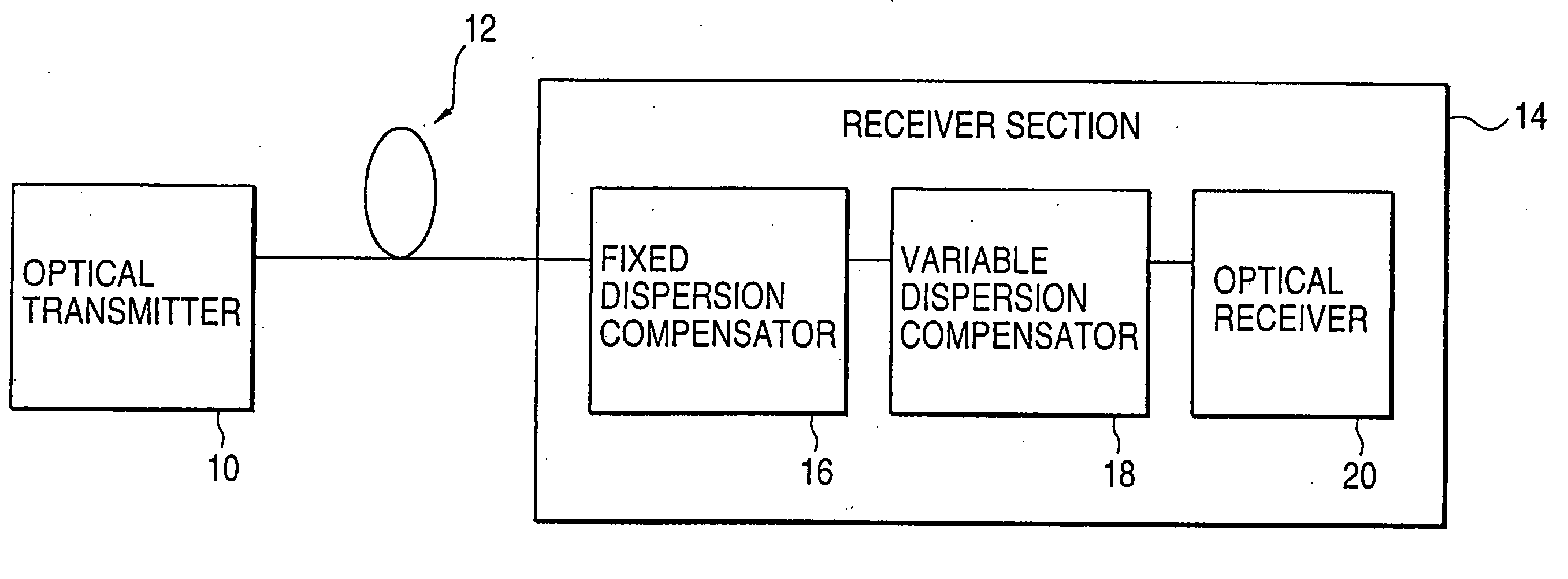
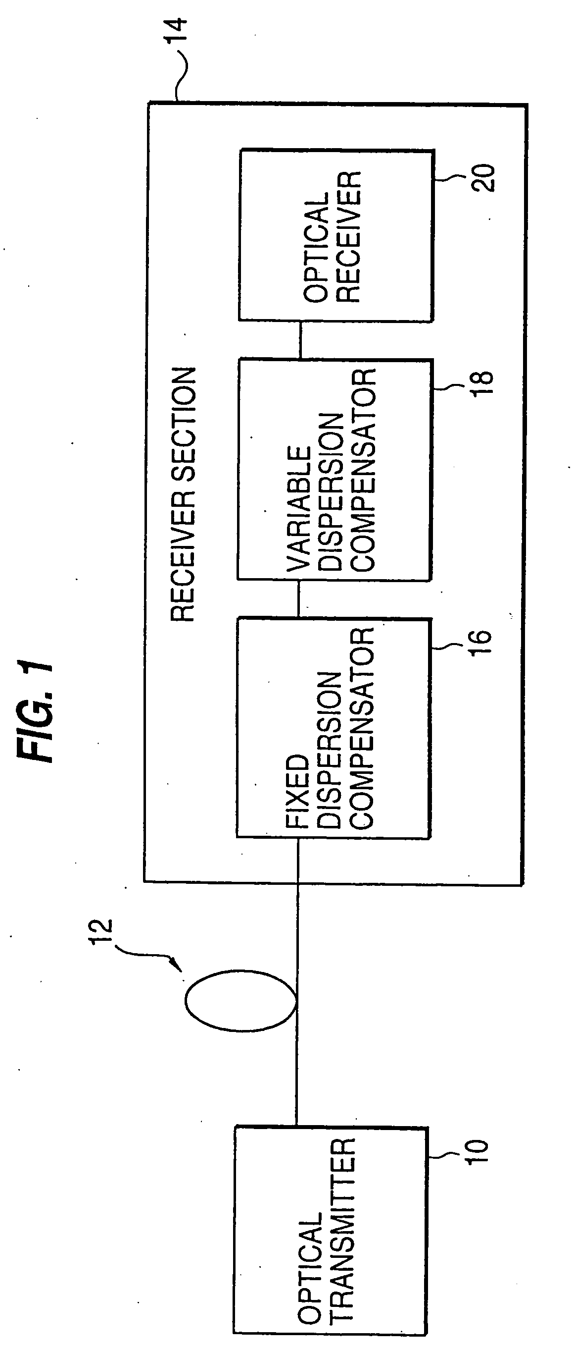
[0055]FIG. 1 is a diagram illustrating an optical transmission system, according to an embodiment of the present invention. Referring now to FIG. 1, a transmitter 10 outputs an optical signal through an SMF 12. For example, the optical signal is at 1.55 μm wavelength and 40 Gb / s transmission speed, and SMF 12 has zero dispersion at 1.3 μm. The optical signal is received by a receiver section 14 having an optical receiver 20. A fixed dispersion compensator 16 and a variable dispersion compensator 18 are also located in receiver section 14. Fixed dispersion compensator 16 has a dispersion amount which is preferably selected from several choices according to the length of SMF 12. Variable dispersion compensator 18 is capable of varying the amount of di...


PUM


Abstract

An apparatus which compensates for dispersion in an optical transmission line. The apparatus includes a fixed dispersion compensator and a variable dispersion compensator. The fixed dispersion compensator has a fixed dispersion amount and coarsely compensates for the dispersion in the transmission line. The variable dispersion compensator has a variable dispersion amount and finely compensates for the dispersion in the transmission line. The fixed and variable dispersion compensators can be located at many positions. For example, one may be in a transmitter and the other may be in a receiver. Both may be in the transmitter and / or the receiver. One may be in either the transmitter or the receiver, with the other in an optical repeater positioned along the transmission line.

Description

CROSS-REFERENCE TO RELATED APPLICATIONS [0001] This application is based on, and claims priority to, Japanese application number 9-243877, filed Sep. 9, 1997, in Japan, and which is incorporated herein by reference. BACKGROUND OF THE INVENTION [0002] 1. Field of the Invention [0003] The present invention relates to an apparatus which compensates for dispersion in an optical fiber transmission line. More specifically, the present invention relates to an apparatus which includes a fixed dispersion compensator for coarse compensation and a variable dispersion compensator for fine compensation. [0004] 2. Description of the Related Art [0005] Optical transmission systems using fiber optical transmission lines are being used to transmit relatively large amounts of information. For example, optical transmission systems at 10 Gb / s are now in practical use. However, as users require larger amounts of information to be rapidly transmitted, a further increase in the capacity of optical transmi...

Claims


Application Information

Patent Timeline
Patent Type & Authority Applications(United States)
IPC IPC(8): G02B6/00H04B10/07H04B10/25H04B10/2507H04B10/2519H04B10/2525H04B10/255H04B10/291
CPCH04B10/2519H04B2210/254H04B2210/252H04B10/2525
Inventor ISHIKAWA, GEORGE
Owner FUJITSU LTD
Why Eureka
Try Eureka