Ultrasonic probe with detachable slidable cauterization forceps

a technology of cauterization forceps and ultrasonic probes, which is applied in the field of ultrasonic tissue ablation instruments and ultrasonic medical treatment devices with electrocautery, can solve the problems of affecting the effect of surgical forceps, and affecting the safety of patients

Active Publication Date: 2005-08-25
MISONIX INC
View PDF20 Cites 124 Cited by
  • Summary
  • Abstract
  • Description
  • Claims
  • Application Information

AI Technical Summary

Benefits of technology

[0013] It is a more specific object of the present invention to provide such an ultrasonic ablation and cauterization probe assembly with improved cauterization function.
[0015] A further object of the present invention is to provide such an ultrasonic ablation and cauterization probe assembly with enhanced visualization.
[0017] A surgical device in accordance with the present invention comprises a forceps member having at least one prong, the prong being formed as an electrode. At least one electrical connector is provided on the forceps member for operatively connecting the prong to an electrical power source. The surgical device further comprises a mechanical connector attached to the forceps member for removably fastening the forceps member to a housing of an ultrasonic probe. The forceps member can thus function to carry out a cauterization procedure during a surgical operation utilizing the probe for ultrasonic ablation.
[0018] The mechanical connector may take the form of a spring clip with a slotted circular configuration for facilitating not only an attachment and subsequent detachment of the forceps member from the housing of the ultrasonic probe (for disposability, to ensure insulation integrity for each surgical procedure) but also a slidable fastening the forceps member to the housing of the probe so that the forceps member is alternatively movable in a distal direction and a proximal direction parallel to an axis of the probe.
[0020] In one embodiment of the present invention, the prong includes a third bend generally towards a distal tip of the probe. In this case, the prong is provided with a V-shape portion disposed outside of the plane of the forceps axis and the probe axis, to provide better visibility of the tip. The third bend is located distally of the second bend, while the second bend is located distally of the first bend. In this embodiment and others, the prong has a distal tip distally advanced with respect to an operating tip of the probe in a distal position of the forceps member relative to the housing.

Problems solved by technology

When the vibrating tip is placed against viable or diseased tissue, the moving tip ablates the cells and causes them to fragment or otherwise emulsify in the irrigation fluid that is being added simultaneously.
One side effect of any surgery is bleeding when the veins, arteries or capillaries are severed.
However, the capillaries and small vessels will be compromised upon exposure to high amplitude ultrasonic tools.
This situation repeats itself often in the course of the operation, lengthening the time of the procedure and coincidently the risk to the patient.
However, as large as the plate is, some collateral damage occurs away from the bleeder site.
This collateral damage cannot be controlled reliably by the physician and is of great concern when operating on the brain.
If the damage is too widespread, mental capacity or nerve structures may be affected negatively.
Again, neurological damage may occur in some organs that are susceptible to damage due to this current, such as the brain, heart and nerve bundles.
However, all of the detriments of monopolar cautery still exist.
In addition, the piezoelectric crystals of the ultrasonic transducer stack must be isolated from the cautery voltage or damage to the transducer or electronics will occur.

Method used


Image

  • Ultrasonic probe with detachable slidable cauterization forceps
  • Ultrasonic probe with detachable slidable cauterization forceps
  • Ultrasonic probe with detachable slidable cauterization forceps

Examples


Embodiment Construction

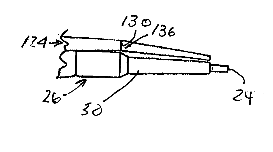
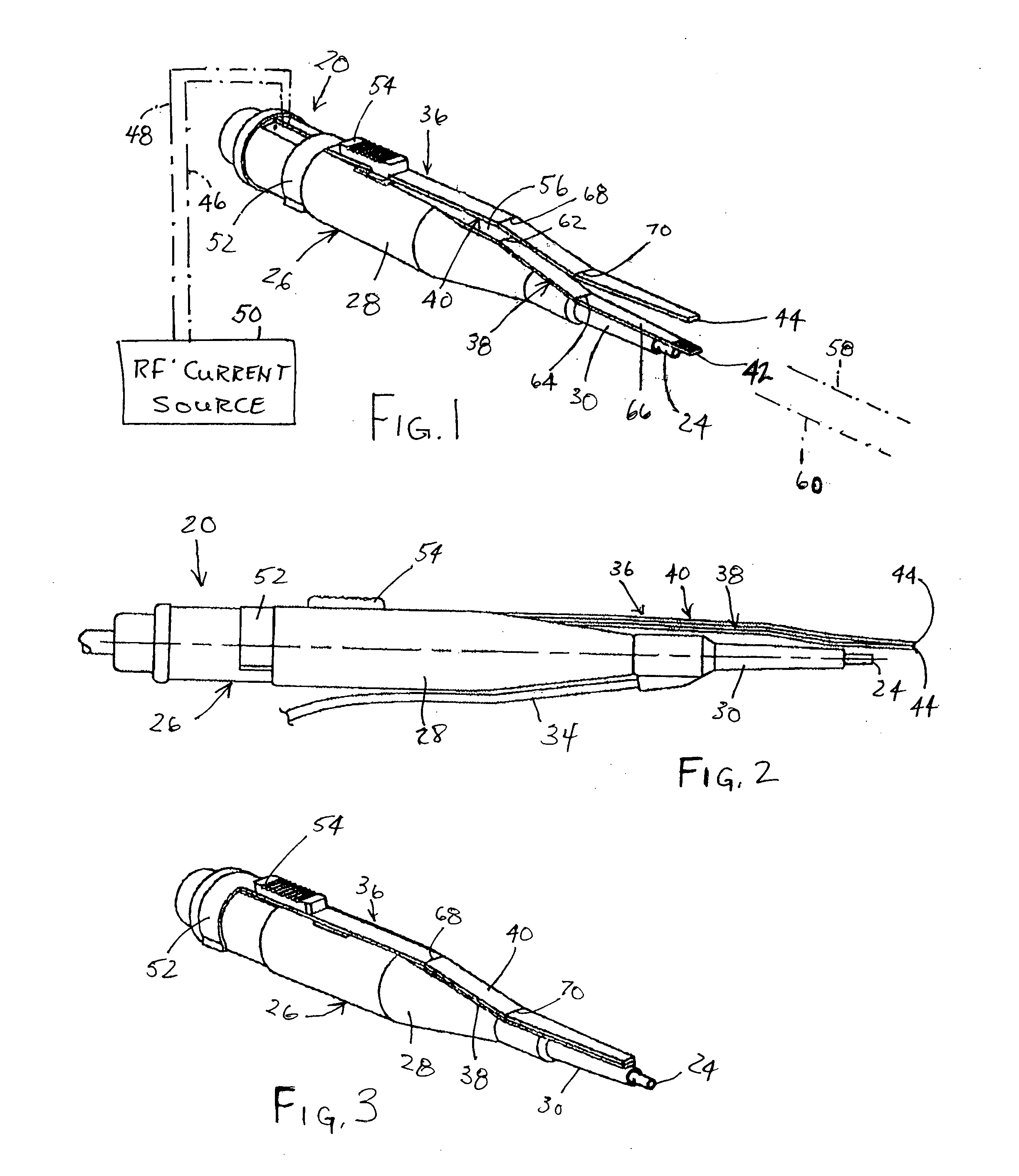
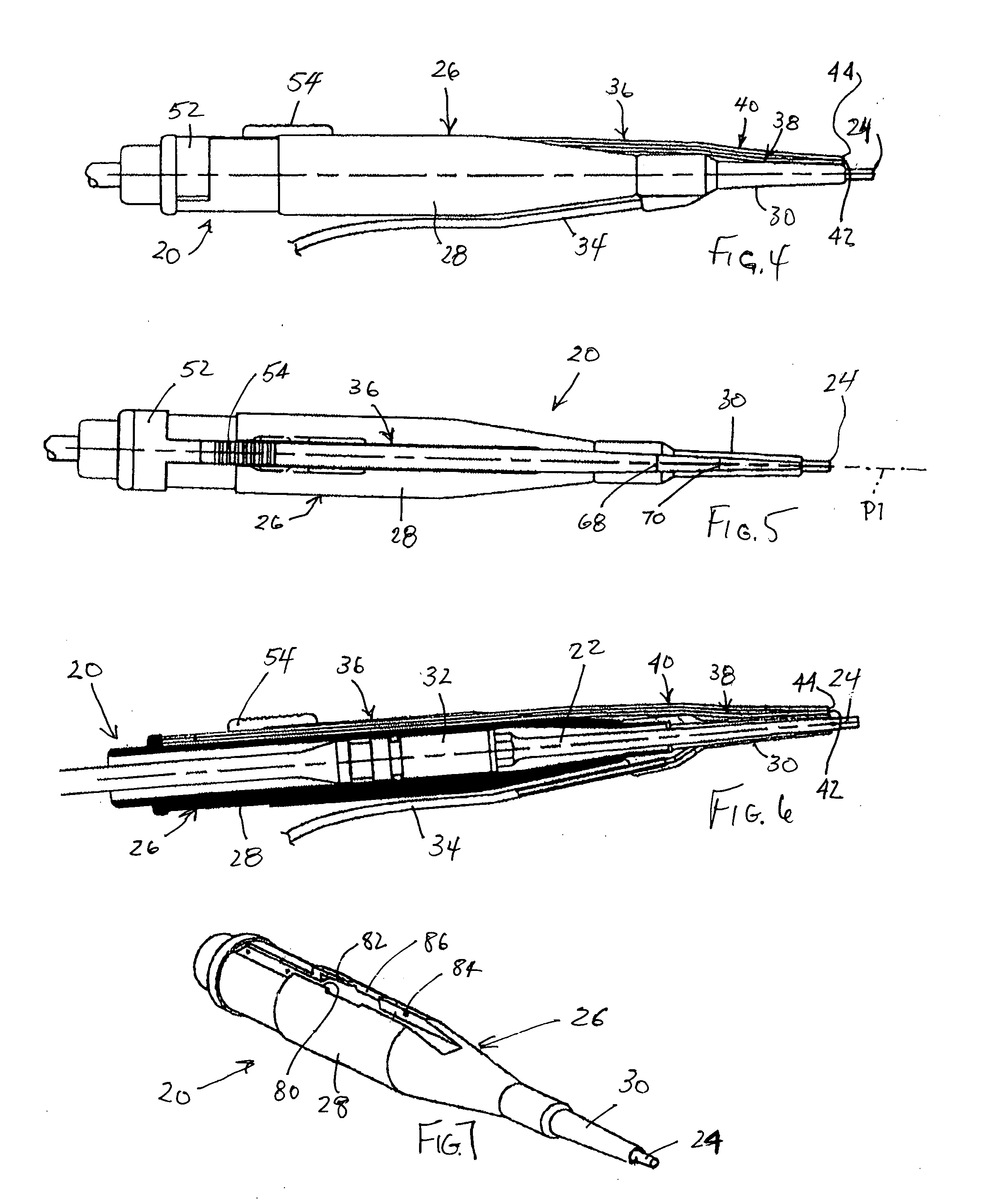
[0042] As illustrated in FIGS. 1-6, a surgical instrument assembly for ultrasonic ablation and RF cauterization includes an ultrasonic instrument 20 having an ultrasonic probe or horn 22 (FIG. 6) enclosed, except for an operative tip 24, in a casing 26. Casing 26 includes a housing portion 28 towards a proximal end of the instrument assembly and a sheath 30 at a distal end of the assembly. Casing further includes a handle (not shown) than is connected to a proximal end of housing portion 28 via an elbow joint (not shown). Sheath 30 surrounds a distal end portion of horn or probe 22. The ultrasonic instrument 20 further includes a piezoelectric transducer array (not shown) connected to a front driver 32 (FIG. 6) for generating ultrasonic standing waves in probe 22. A tube 34 is connected to casing 26 for irrigation. Suction is provided via an internal passage through the probe 22.

[0043] As illustrated in FIGS. 1-6, the surgical instrument assembly further includes a forceps member 3...


PUM


Abstract

A surgical device for ultrasonic ablation and RF cauterization includes a forceps member having at least one prong, the prong being formed as an electrode. At least one electrical connector is provided on the forceps member for operatively connecting the prong to an electrical power source. The surgical device further includes a mechanical connector attached to the forceps member for removably fastening the forceps member to a housing of an ultrasonic probe. The forceps member can thus function to carry out a cauterization procedure during a surgical operation utilizing the probe for ultrasonic ablation.

Description

FIELD OF THE INVENTION [0001] This invention relates to a medical device and more specifically to an ultrasonic tissue ablation instrument. Even more specifically, this invention relates to an ultrasonic medical treatment device with electrocautery. This invention also relates to an associated medical treatment method. BACKGROUND OF THE INVENTION [0002] Many diseases of the brain and spine require surgery to provide the patient with relief. These could include cancer, non-malignant lesions and trauma induced by accidents or physical attack. As a procedure, neurosurgery has been practiced for several millennia. Archeologists have discovered evidence of sophisticated cranial surgery in relics and skulls dating back to Roman times. The tools found have been shown to be remarkably similar to today's designs. Of course, modern science has substantially improved upon the techniques and results obtained in those days. [0003] One of the biggest steps forward occurred approximately 30 years ...

Claims


Application Information

Patent Timeline
Patent Type & Authority Applications(United States)
IPC IPC(8): A61B17/00A61B17/20A61B17/32A61B18/04A61B18/14
CPCA61B17/320068A61B17/320092A61B2018/1495A61B2017/00477A61B2018/1462A61B18/1442A61B2017/320084
Inventor ISOLA, SCOTT S.NOVAK, THEODORE A. D.DARIAN, ALEXANDER L.MANNA, RONALD R.
Owner MISONIX INC
Why Eureka
Try Eureka