Hair removal device with disc and vibration assemblies

Inactive Publication Date: 2005-08-25
SOFT LINES
View PDF33 Cites 32 Cited by
  • Summary
  • Abstract
  • Description
  • Claims
  • Application Information

AI Technical Summary

Problems solved by technology

Although razors provide quick and easy hair removal, hair remains visible at the surface of the skin and quickly regrows.
However, removing hair with tweezers is a tedious process since traditional tweezers can only remove one hair at a time and precise handling of the tweezers is required in order to posi

Method used


Image

  • Hair removal device with disc and vibration assemblies
  • Hair removal device with disc and vibration assemblies
  • Hair removal device with disc and vibration assemblies

Examples


Embodiment Construction

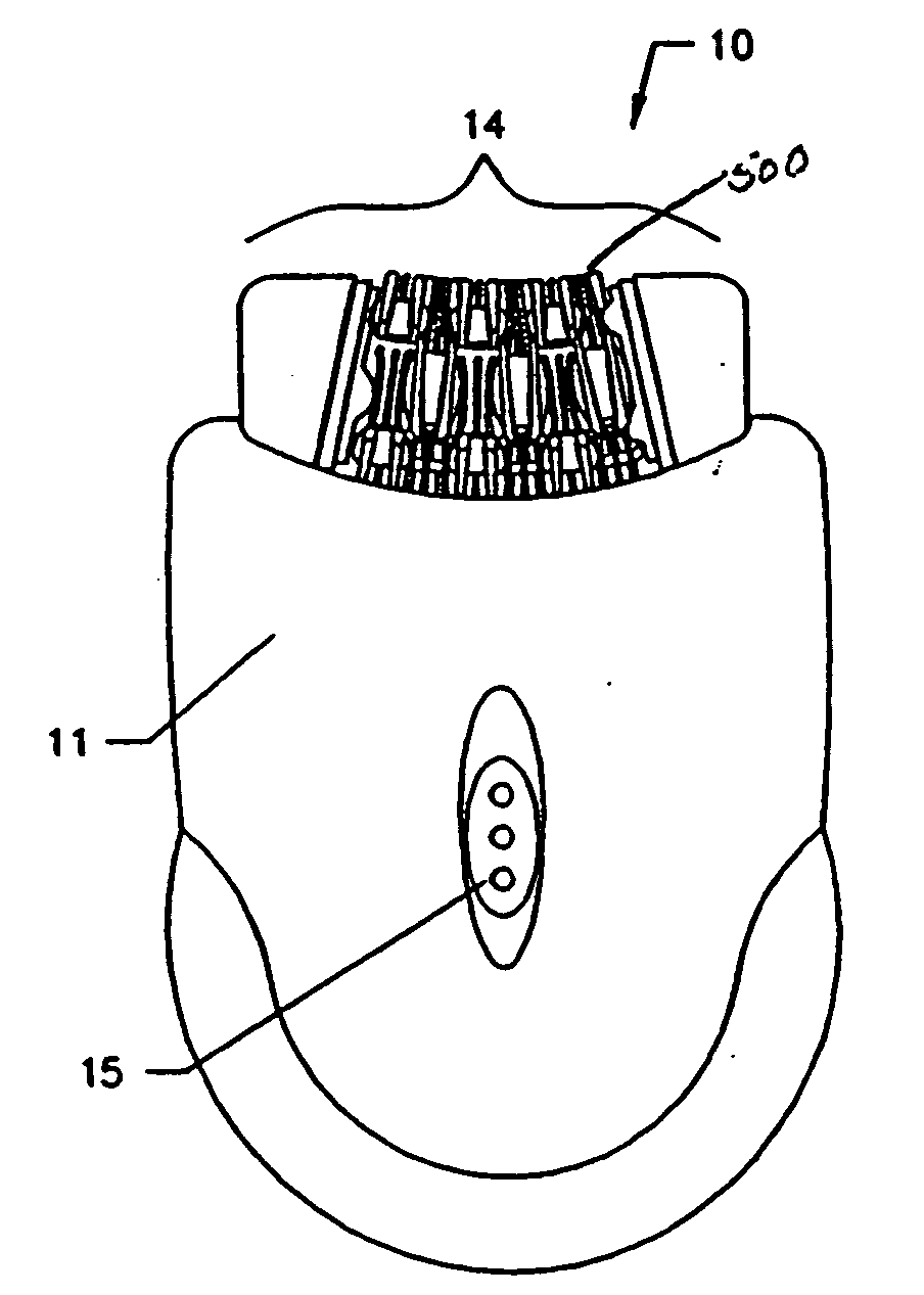
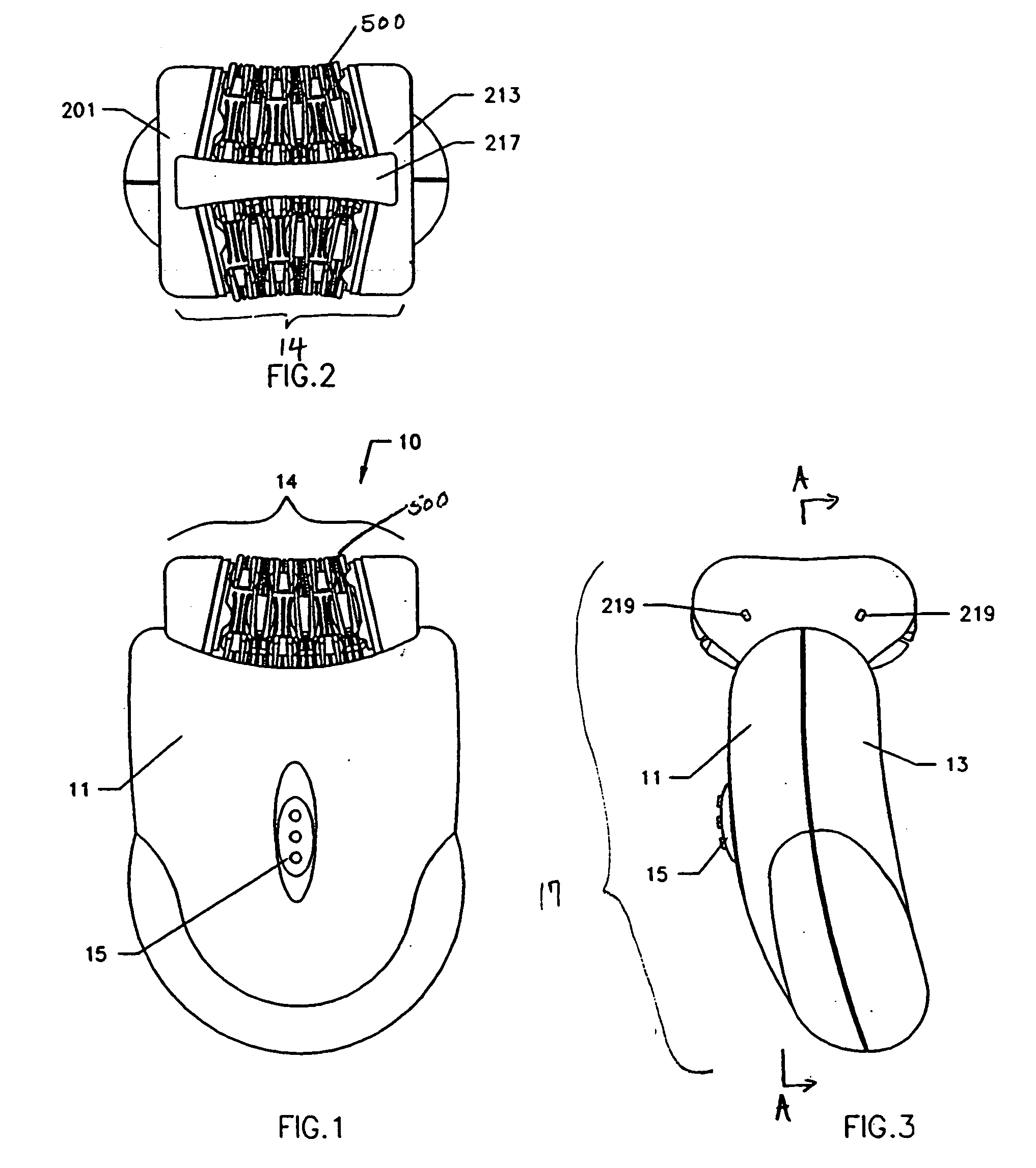
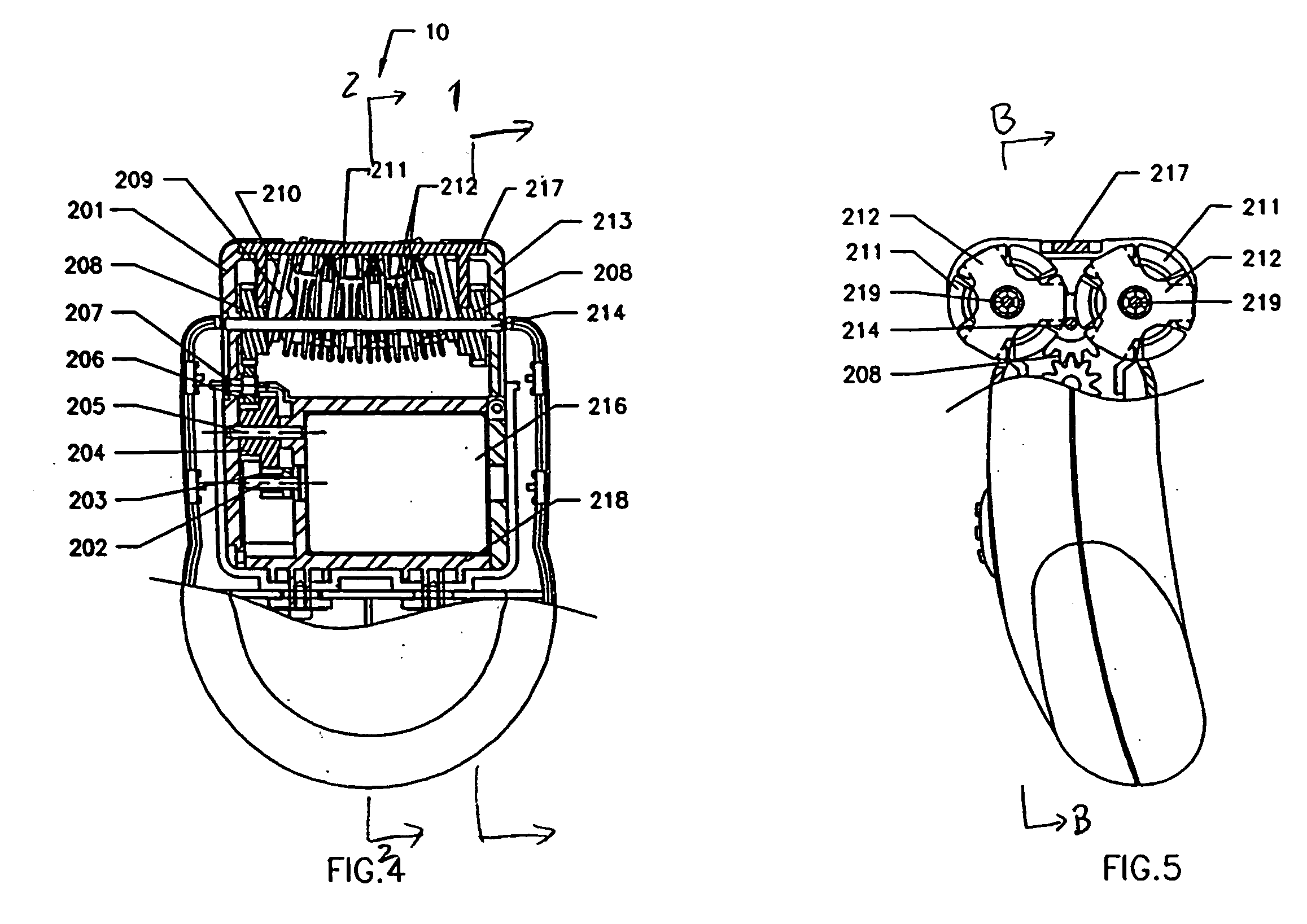
[0026]FIGS. 1-12 illustrate a preferred embodiment of the hair removal device 10 according to the present invention. As shown in FIGS. 1-12, hair removal device 10 preferably includes a hair-plucking assembly 14 (FIGS. 1, 2), a vibration assembly 603 (FIG. 9), a driving assembly 216, 202-207 (FIGS. 4, 6), and a housing 17 (FIG. 3).

[0027] As shown in FIGS. 1-2, hair-plucking assembly 14 preferably includes, among other components described further below, a plurality of disc assemblies 500. A preferred embodiment of disc assembly 500 is illustrated in further detail in FIGS. 7-9. As shown in FIG. 7, each disc assembly 500 preferably includes three main elements: an internal disc assembly 301 and two outer discs 212. Each internal disc assembly 301 includes a disc carrier 302 and an insert disc 501. Each disc carrier 302, in turn, includes U-shaped members 305, opposing pinchers 306, engagement protrusions 303, and engagement recessions 304. Each insert disc 501 and outer disc 212 inc...


PUM


Abstract

A device for removing unwanted hair, including a hair-plucking assembly, and a vibration assembly, a driving assembly, and a housing. The hair-plucking assembly includes two groups of disc assemblies that remove hair as they rotate. As the hair-plucking assembly removes hair, the vibration assembly vibrates to massage the area of hair removal to minimize discomfort associated with the hair removal.

Description

[0001] This is a continuation-in-part of application Ser. No. 09 / 246,454, filed Feb. 9, 1999 and will issue on Sep. 26, 2000 as U.S. Pat. No. 6,123,713, which is itself a continuation-in-part of application Ser. No. 09 / 112,971, filed Jul. 9, 1998 and issued Nov. 2, 1999 as U.S. Pat. No. 5,976,157. We incorporate both patents by reference in their entirety.FIELD OF THE INVENTION [0002] The present invention relates generally to a depilatory device for removal of unwanted hair, and more specifically, to a device for removing unwanted hair by trapping and uprooting the hair while at the same time massaging the hair-removal area to reduce discomfort associated with hair removal. BACKGROUND OF THE INVENTION [0003] There exists a need for removal of unwanted hair in order to maintain a desirable physical appearance. There are many devices known in the art that are useful for removing unwanted hair such as razors, tweezers and other depilatory devices. Although razors provide quick and eas...

Claims


Application Information

Patent Timeline
IPC IPC(8): A45D26/00
CPCA45D26/0061A45D26/0028
Inventor YIU, WAI-WAH
Owner SOFT LINES
Why Eureka
Try Eureka