Path control method
a control method and path technology, applied in the field of storage devices and information processing apparatuses, can solve the problems of delay in writing response, packet transmission of the entire system, and congestion, and achieve the effects of reducing the throughput of packet transmission, and reducing the number of errors
- Summary
- Abstract
- Description
- Claims
- Application Information
AI Technical Summary
Benefits of technology
Problems solved by technology
Method used
Image

Examples
first embodiment
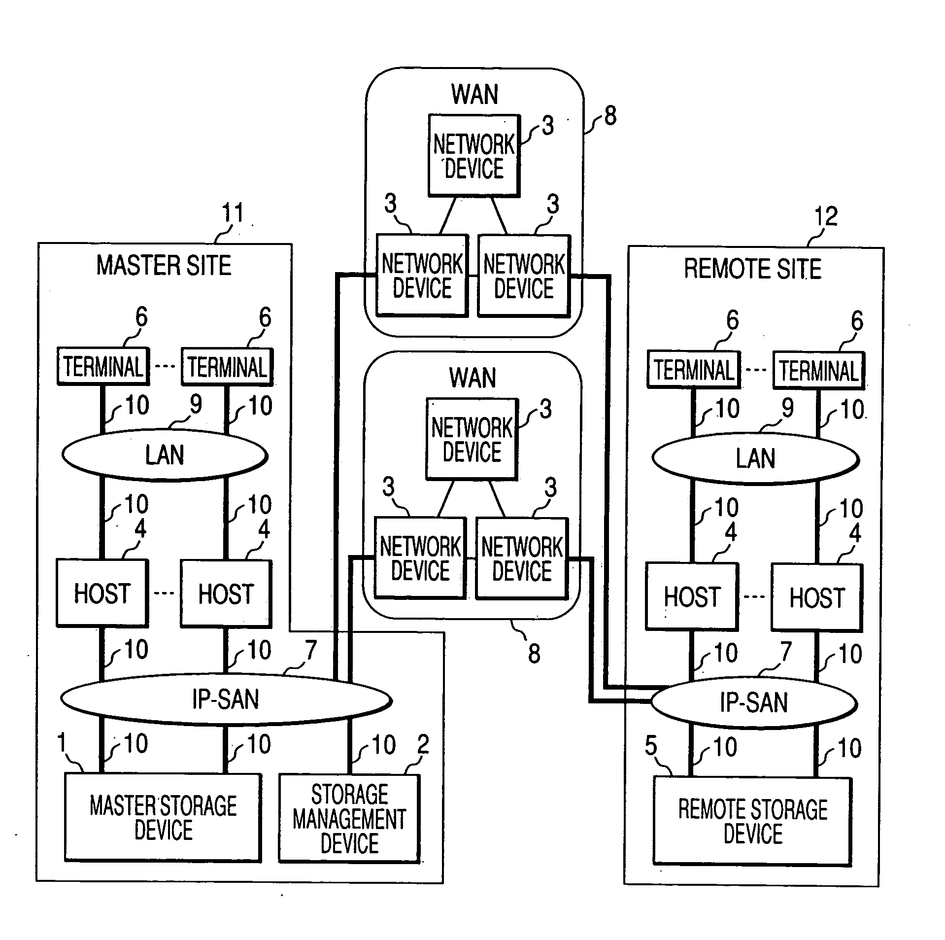
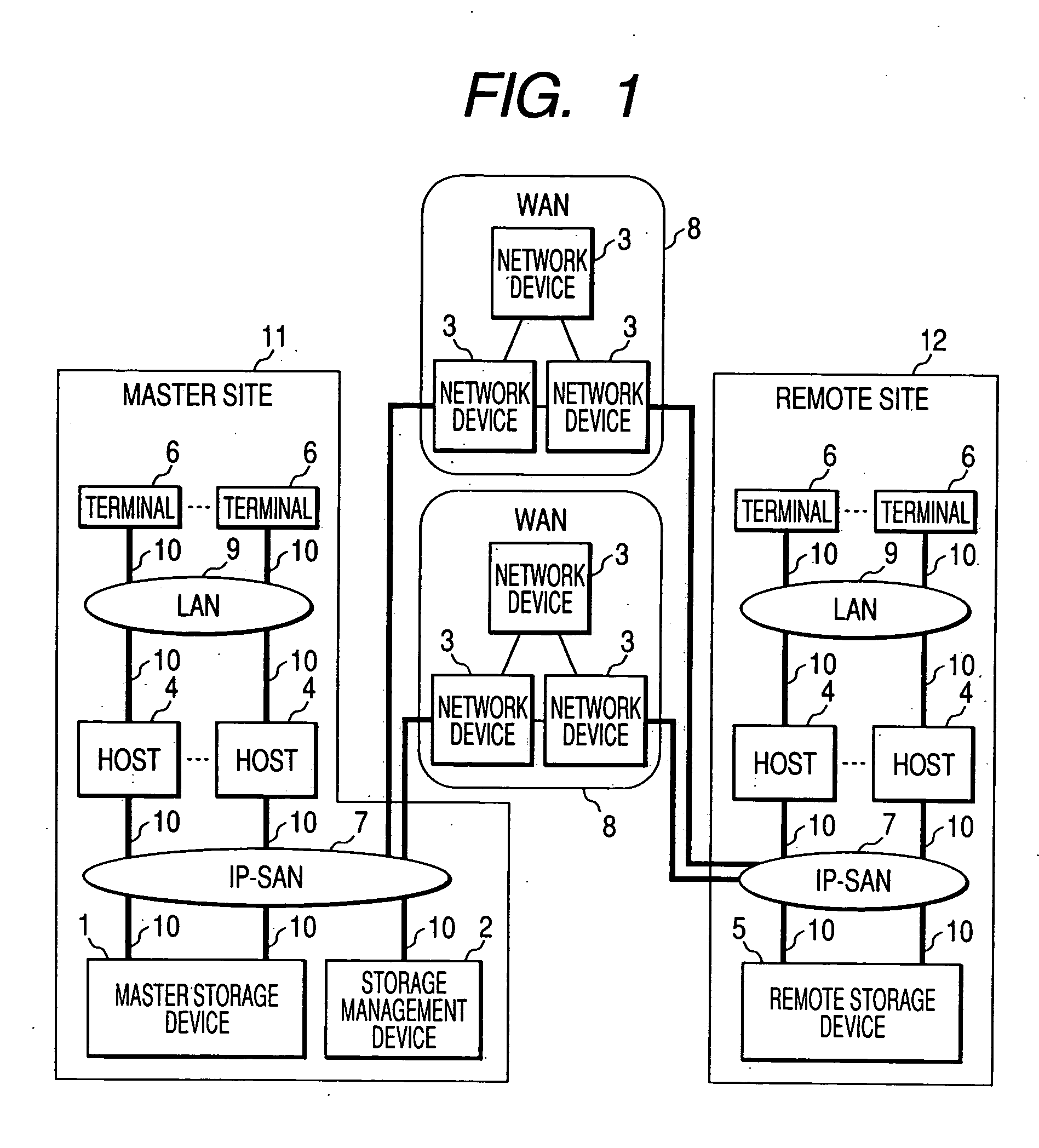
[0048]FIG. 1 is a diagram showing an example of a structure of the system of the The system includes a master site 11, a remote site 12, and one or more WANs (Wide Area Networks) 8 which connect these sites. Note that “site” indicates a location where devices are set or a group of devices, for example, one building. In addition, in this embodiment, it is assumed that the master site 11 and the remote site 12 are apart from each other by a certain distance (e.g., the master site in Tokyo and the remote site in Osaka).
[0049] The master site 11 includes: a maser storage device 1; a storage management device 2 which manages the master storage device 1; hosts 4; terminals 6; an IP-SAN 7 which is an IP network connecting the hosts 4, the master storage device 1, and the storage management device 2; and a LAN 9 which is an IP network connecting the terminals 6 and the hosts 4. In addition, the master storage device 1, the storage management device 2, and the hosts 4 are connected to the I...
third embodiment
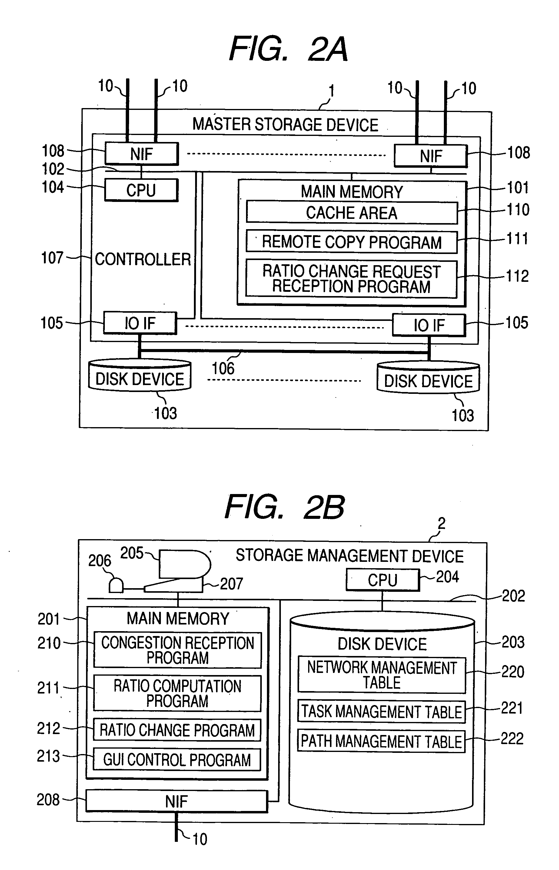
[0144]FIG. 15B is a diagram showing an example of a structure of the storage management device 2 in the In this embodiment, the storage management device 2 is only an input terminal for configuration information. Therefore, a GUI control program 213 and a configuration transmission program 215, which is executed by the CPU 204 in sending configuration contents inputted by the system administrator or the like to the master storage device 1, are stored in the main memory 201 of the storage management device 2. No table related to the present invention is stored in the disk device 203.
[0145] In the third embodiment, the system administrator or the like sets respective parameters on the remote copy task registration screen 700, which is displayed on the display 205, using the character input device 207 and the pointing device 206. Thereafter, when the system administrator or the like designates the button 716, the button 717, or the button 728, a configuration transmission program 215 ...
fourth embodiment
[0165] In the fourth embodiment, the master storage device 1 considers that congestion has occurred in the case in which an ACK, which is sent from the remote storage device 5 in a TCP connection used for remote copy, is not returned when time is out, that is, when a fixed period has elapsed or in the case in which three or more ACKs having the same sequence number have been received. These operations are based upon specifications of TCP defined by RFC793 and RFC2581, respectively.
[0166] In the case in which congestion occurrence is detected by the above-mentioned operation, the master storage device 1 performs the path management table update processing and the ratio computation processing described in FIGS. 10, 11 and 12 and executes remote copy using a ratio among paths after change which is obtained as a result of the processing.
[0167] On the other hand, the RFC does not define with which opportunity it is considered that congestion recovery has taken place. Thus, in the fourth...
PUM
 Abstract
Description
Claims
Application Information
 - Generate Ideas
- Intellectual Property
- Life Sciences
- Materials
- Tech Scout
- Unparalleled Data Quality
- Higher Quality Content
- 60% Fewer Hallucinations
Browse by: Latest US Patents, China's latest patents, Technical Efficacy Thesaurus, Application Domain, Technology Topic, Popular Technical Reports.
© 2025 PatSnap. All rights reserved.Legal|Privacy policy|Modern Slavery Act Transparency Statement|Sitemap|About US| Contact US: help@patsnap.com