

Internal combustion engine
- Summary
- Abstract
- Description
- Claims
- Application Information
AI Technical Summary
Benefits of technology
Problems solved by technology
Method used
Image

Examples
Embodiment Construction
[0033] An embodiment of the invention will be hereinafter explained on the basis of the drawings.
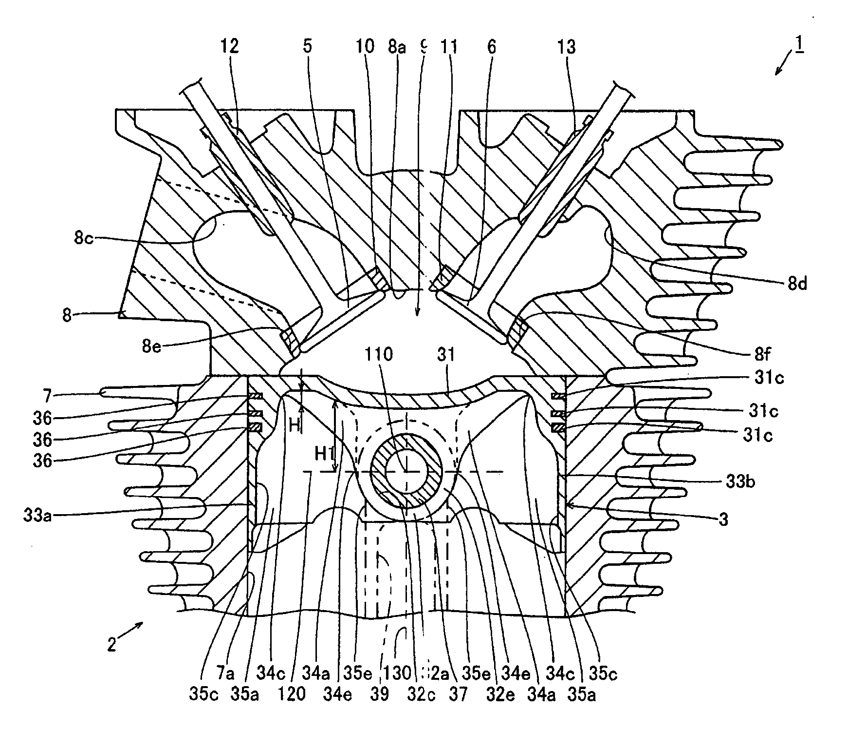
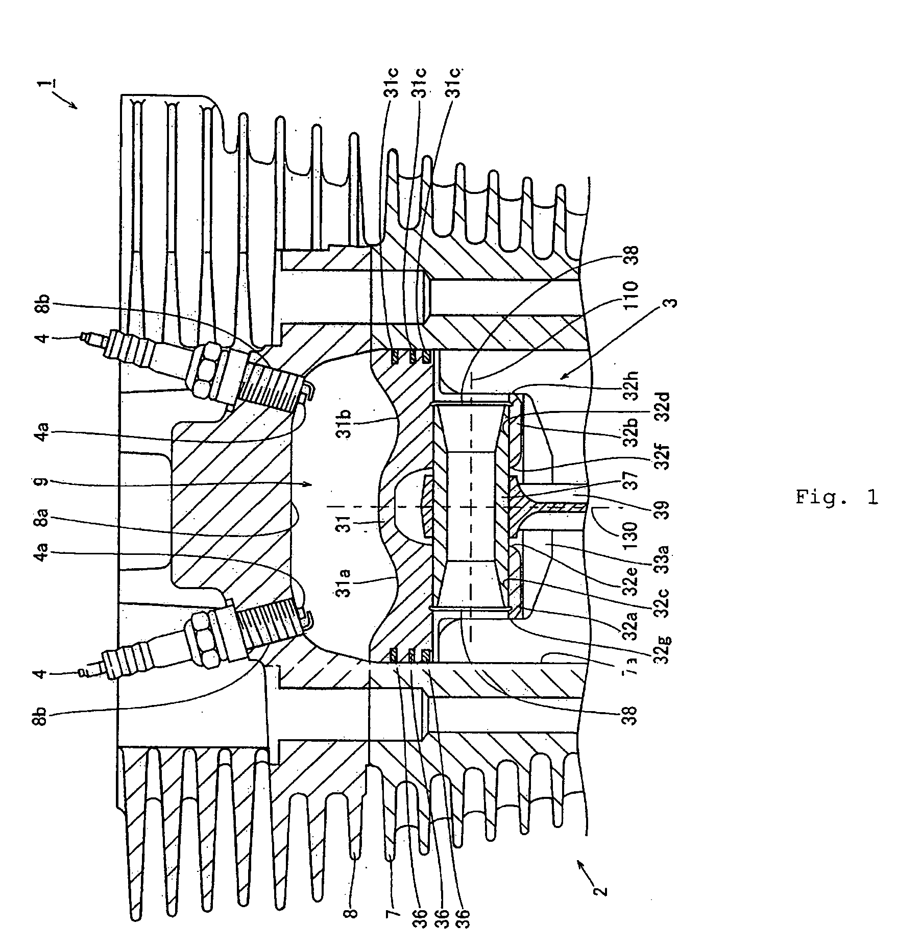
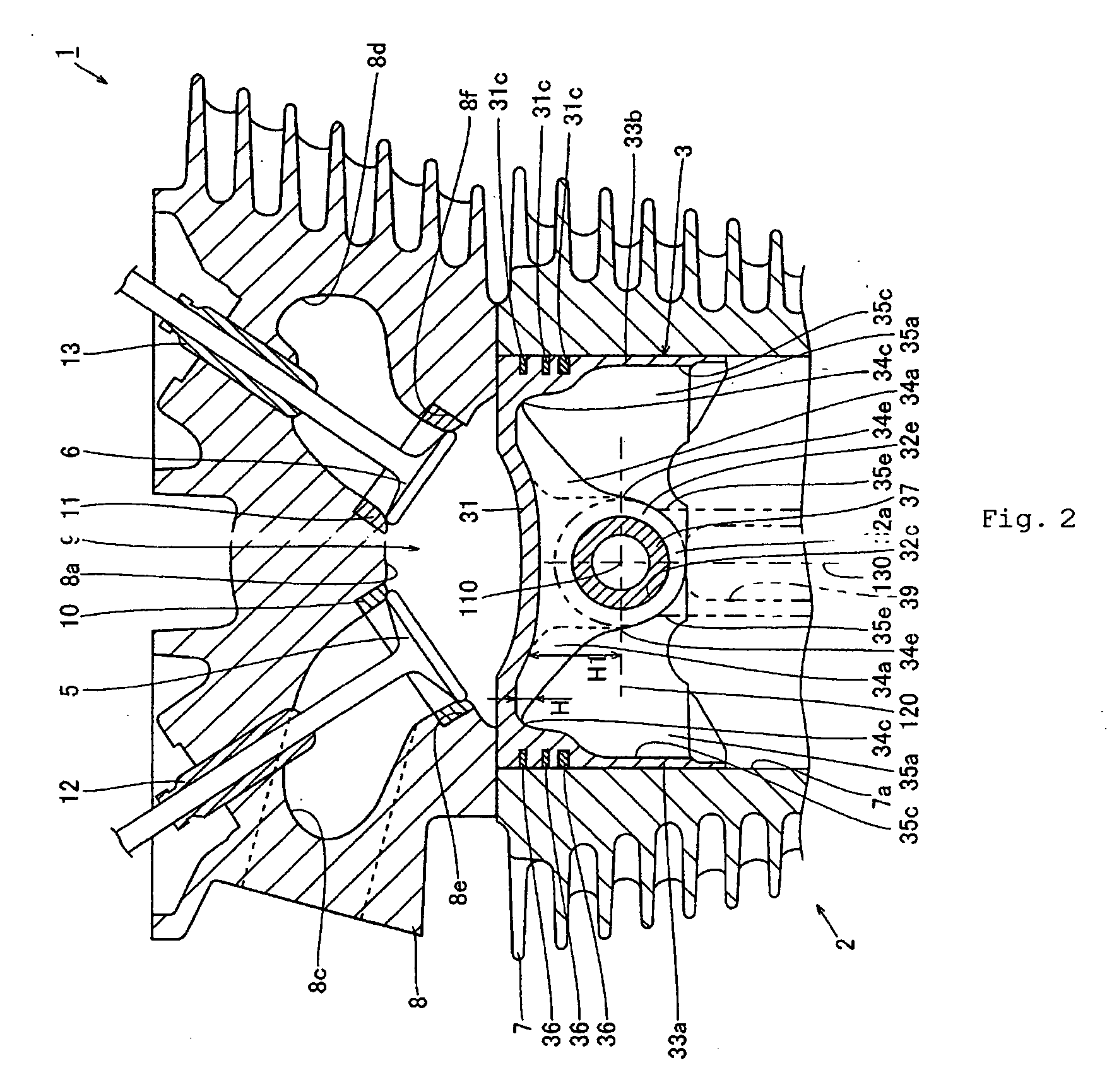
[0034] First, a structure of a four-cycle internal combustion engine 1 in which a piston 3 in the form of a preferred embodiment can be used. All or some of the aspects and features of the present piston design, however, can be used with other types of internal combustion engines; for example, some or all of the aspects and features of the present piston design can be used with engines that have different numbers of cylinders, have different cylinder arrangements, use different ignition schemes, employ different fuel charging devices (e.g., direct fuel injection) and different valve arrangements and operation (e.g., VVT and VVL), and / or operate on different combustion principles (e.g., a two-stroke internal combustion engine).
[0035] As shown in FIGS. 1 and 2, the four-cycle internal combustion engine 1 according to this embodiment includes a cylinder 2, a piston 3 preferably of aluminu...
PUM
 Abstract
Description
Claims
Application Information