System and method for multi-lift valve actuation

a multi-lift valve and valve actuation technology, applied in the direction of valve drives, machines/engines, non-mechanical valves, etc., can solve the problems of difficulty in adjusting the timing and/or amount of engine valve li

Active Publication Date: 2005-09-01
JACOBS VEHICLE SYST
View PDF6 Cites 20 Cited by
  • Summary
  • Abstract
  • Description
  • Claims
  • Application Information

AI Technical Summary

Benefits of technology

[0013] Responsive to the foregoing challenges, Applicant has developed innovative systems and methods for actuating one or more engine valves. In one embodiment, the system may comprise: a housing; an accumulator disposed in the housing having a first open end and a second open end; a master piston slidably disposed in a first bore formed in the housing; a valve train element(s) for impar

Problems solved by technology

The use of fixed profile cams, however, can make it difficult to adjust the timings and/

Method used


Image

  • System and method for multi-lift valve actuation
  • System and method for multi-lift valve actuation
  • System and method for multi-lift valve actuation

Examples


first embodiment

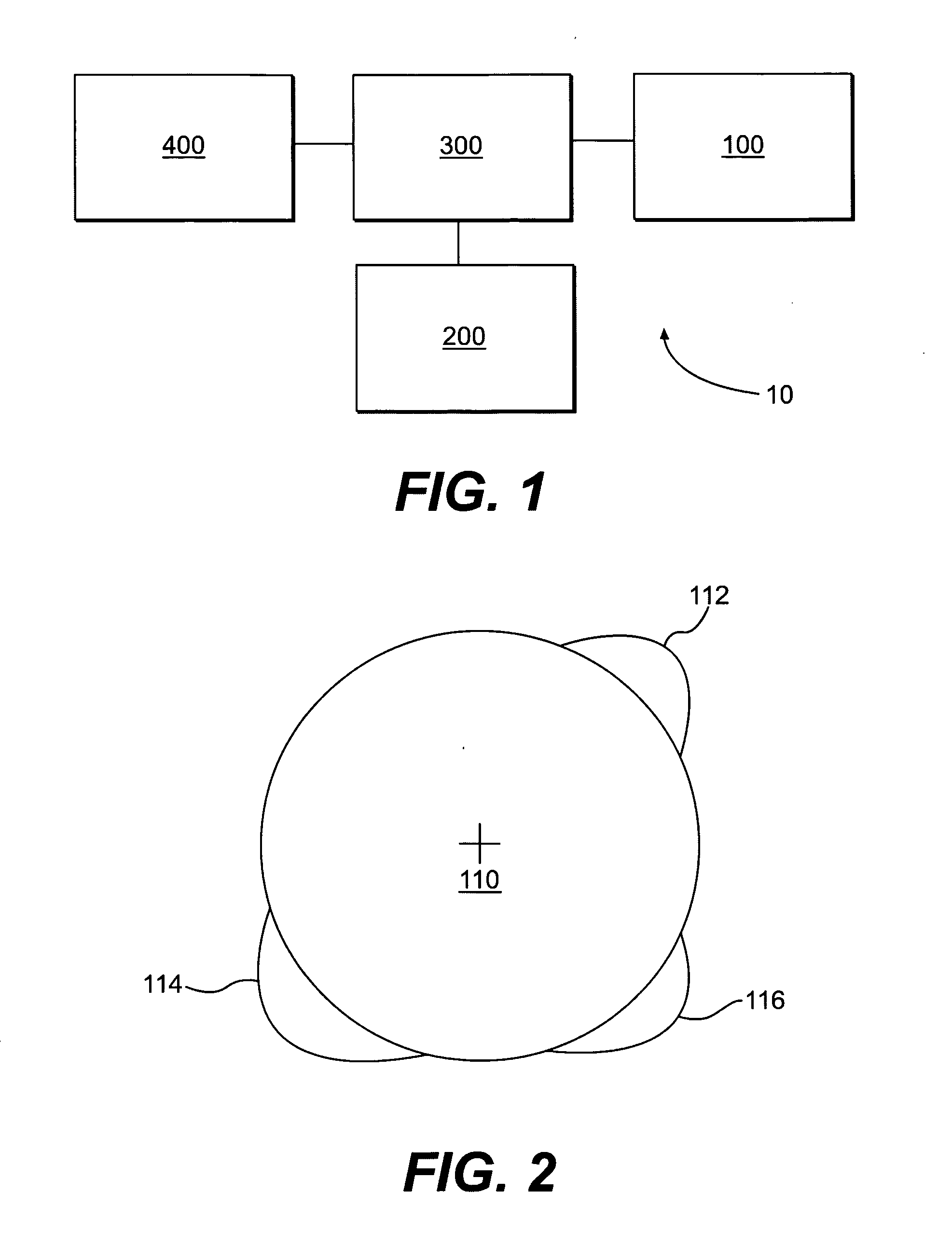
[0024] the present invention is shown schematically in FIG. 1 as valve actuation system 10. The valve actuation system 10 includes a means for imparting motion 100 operatively connected to a valve actuator assembly 300, which in turn is operatively connected to one or more engine valves 200. The motion imparting means 100 is adapted to apply motion to the valve actuator 300. The valve actuator 300 may be selectively controlled to transfer or not transfer motion to the engine valve 200.

[0025] When in the motion transfer mode, the valve actuator 300 is adapted to actuate the engine valve 200 to produce an engine valve event, such as, but not limited to, main intake, main exhaust, exhaust gas recirculation, compression release braking, and / or bleeder braking. The valve actuator 300 may also modify the amount and timing of the motion transferred to the engine valves 200. In this manner, the valve actuator 300 is adapted to provide multiple valve lift profiles. The valve actuation system...

second embodiment

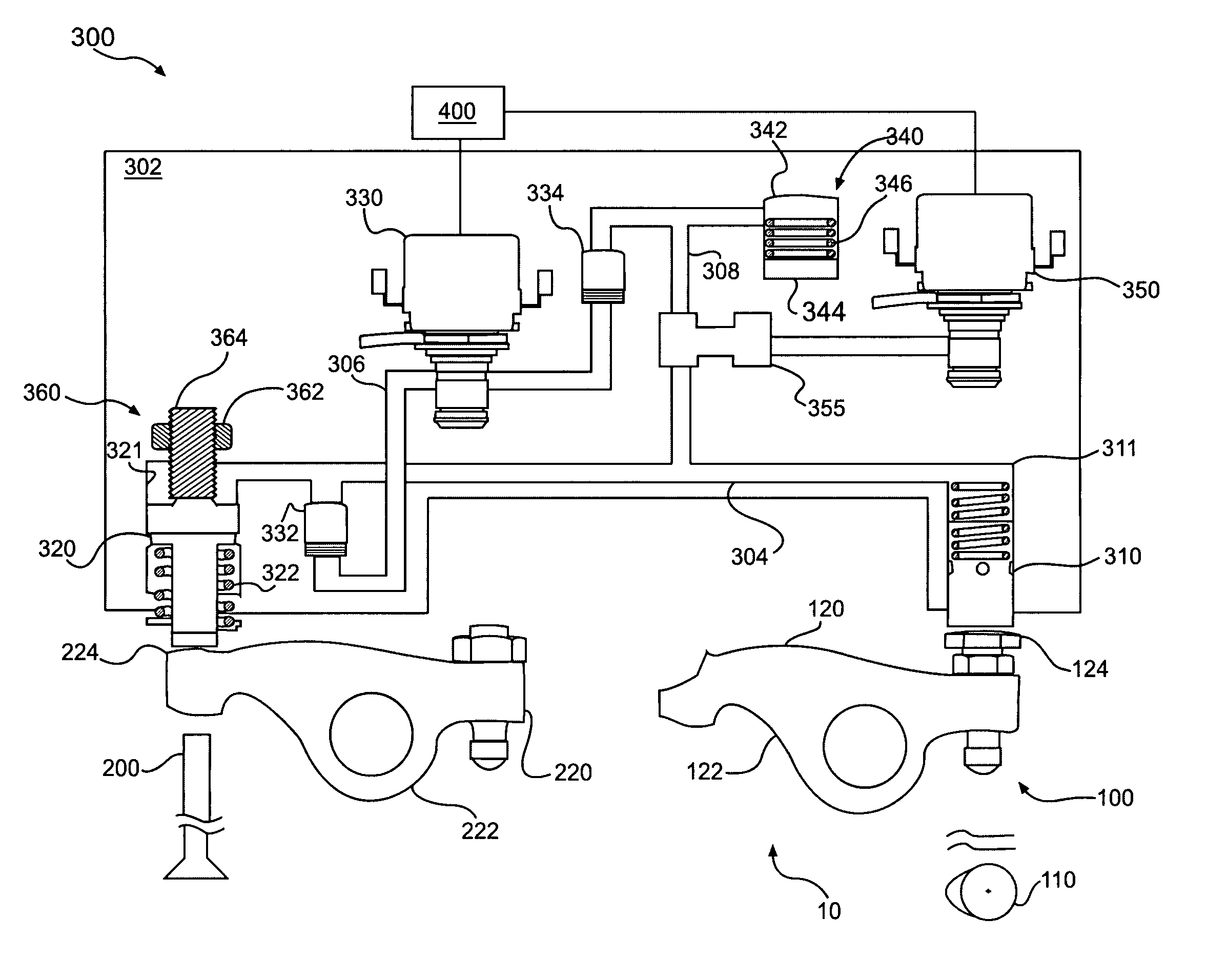
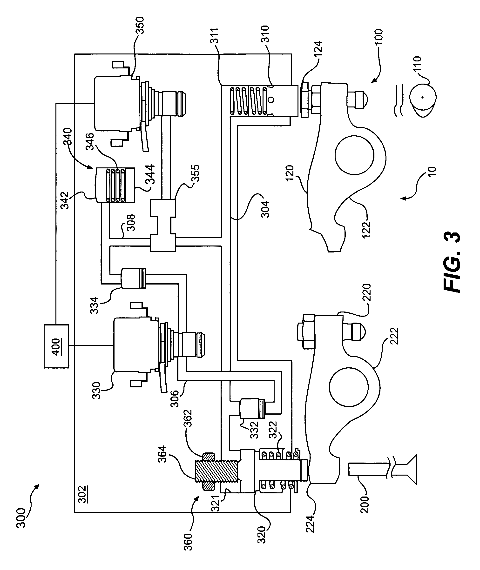
[0030] the present invention will now be described with reference to FIG. 3. The valve actuator 300 comprises master piston assembly 310 slidably disposed in a first bore 311 formed in a housing 302 such that it may slide back and forth in the bore while maintaining a hydraulic seal with the housing 302. The valve actuator 300 further includes a slave piston assembly 320 disposed in a second bore 321 formed in the housing 302 such that it may slide back and forth in the bore while maintaining a hydraulic seal with the housing 302. The slave piston assembly 320 is in fluid communication with the master piston assembly 310 through a hydraulic passage 304 formed in the housing 302. A spring 322 biases the slave piston 320 upward in the bore 321, away from the engine valve 200. The spring 324 holds the slave piston 320 up against any low hydraulic pressure in the passage 304 that may be acting on the piston. This prevents the slave piston assembly 320 from “jacking,” a condition which c...


PUM


Abstract

A system and method for actuating one or more engine valves to produce an engine valve event is disclosed. The system may comprise: a housing; an accumulator disposed in the housing having a first open end and a second open end; a master piston slidably disposed in a first bore formed in the housing; a valve train element(s) for imparting motion to the master piston; and a slave piston slidably disposed in a second bore formed in the housing, the slave piston in fluid communication with the master piston through a high pressure hydraulic passage, wherein the first open end and the second open end of the accumulator are in communication with the high pressure hydraulic passage to selectively modify the imparted motion.

Description

CROSS-REFERENCE TO RELATED PATENT APPLICATION [0001] This application claims priority on U.S. Provisional Patent Application No. 60 / 544,336, for System and Method for Multi-Lift Valve Actuation, filed on Feb. 17, 2004, the entirety of which is incorporated herein by reference.FIELD OF THE INVENTION [0002] The present invention relates generally to a system and method for actuating one or more valves in an engine. In particular, the present invention relates to systems and methods for multi-lift actuation of one or more engine valves to produce an engine valve event. In one embodiment, the present invention may be used to provide multi-lift exhaust gas recirculation valve events. Embodiments of the present invention may provide other multi-lift valve events, such as, for example, main valve events (exhaust and / or intake), compression release braking valve events, bleeder braking valve events, and / or other auxiliary valve events. BACKGROUND OF THE INVENTION [0003] Valve actuation in a...

Claims


Application Information

Patent Timeline
IPC IPC(8): F01L1/08F01L1/20F01L9/14F01L13/06F02D13/02F02D13/04F02M25/07
CPCF01L1/08F01L1/20F01L9/025F01L13/06F01L13/065Y02T10/121F01L2800/10F02D13/0273F02D13/04F02M25/0752F01L2001/34446F02M26/01F01L9/14
Inventor RUGGIERO, BRIANYANG, ZHOUFUCHS, NEILJANAK, ROBBHUANG, SHENGQIANG
Owner JACOBS VEHICLE SYST
Why Eureka
Try Eureka