Bill receiving and paying apparatus

Inactive Publication Date: 2005-09-01
HITACHI OMRON TERMINAL SOLUTIONS CORP
View PDF1 Cites 52 Cited by
  • Summary
  • Abstract
  • Description
  • Claims
  • Application Information

AI Technical Summary

Benefits of technology

[0016] In accordance with the present invention, it is possible to provide a bill receiving and paying apparatus which has a function capable of replenishing and retracting the bi

Problems solved by technology

However, since the recycle cassette is piled up to the above in correspondence to an increase of the money kinds handled by the apparatus, a height of an entire of the apparatus or the cash slot is increased, so that there is generated a problem that the apparatus may not be installed and there is generated a problem that an operability of the user is lowered.
Further, since the reject cassette has the horizontally arranged structure, and is arranged, in the vertically laminated direction in the same manner as the money classifying recycle cassette, the reject cassette tends to be affected by the height limitation of the cash slot, and there is a possibility that it is unavoidable to structure the reject cassette in a small capacity.
In the case that the cap

Method used


Image

  • Bill receiving and paying apparatus
  • Bill receiving and paying apparatus
  • Bill receiving and paying apparatus

Examples


embodiment 1

[0039] A description will be given below of an embodiment of a bill receiving and paying apparatus (also called as a bill handling apparatus) with reference to the accompanying drawings.

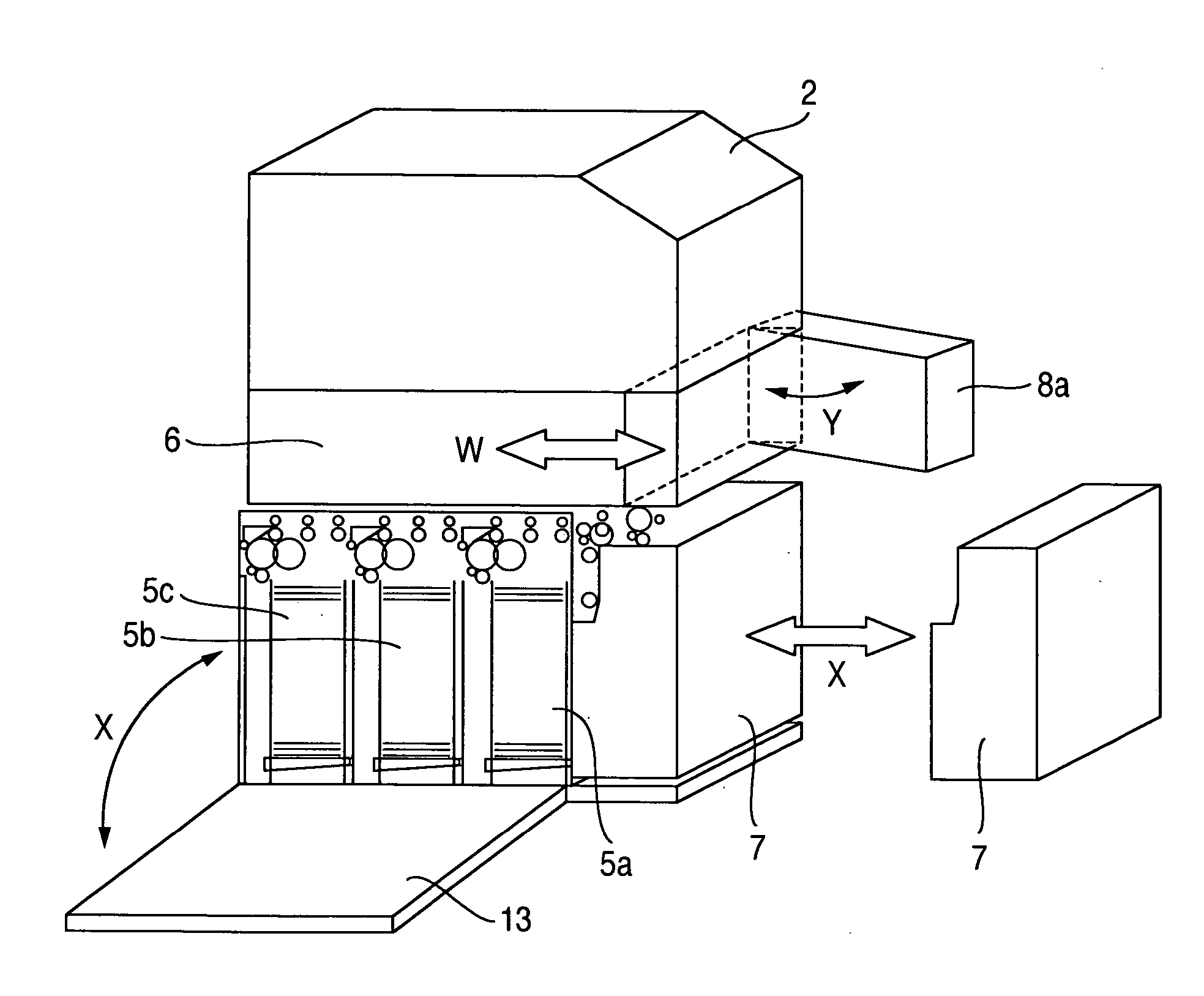
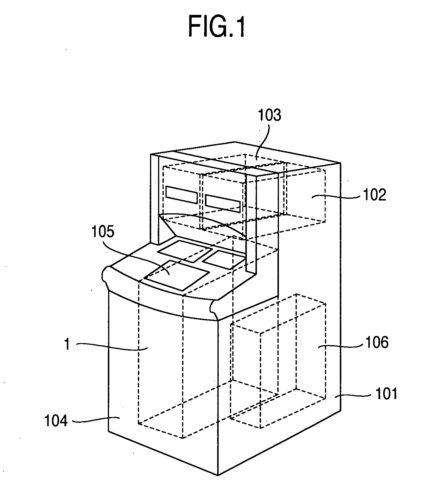
[0040]FIG. 1 shows an outer appearance of an automatic teller machine (ATM) mounting a bill receiving and paying apparatus therein. A constituting element of the automatic teller machine 101 includes a card / account handling mechanism 102 handling a transaction card of a user and a transaction account, a passbook handling mechanism 103 handling a passbook, a casing 104 covering the apparatus, a user operating portion (also called simply as an operating portion) 105 displaying and inputting information necessary for the transaction, and a bill receiving and paying apparatus 1 receiving and paying the bill.

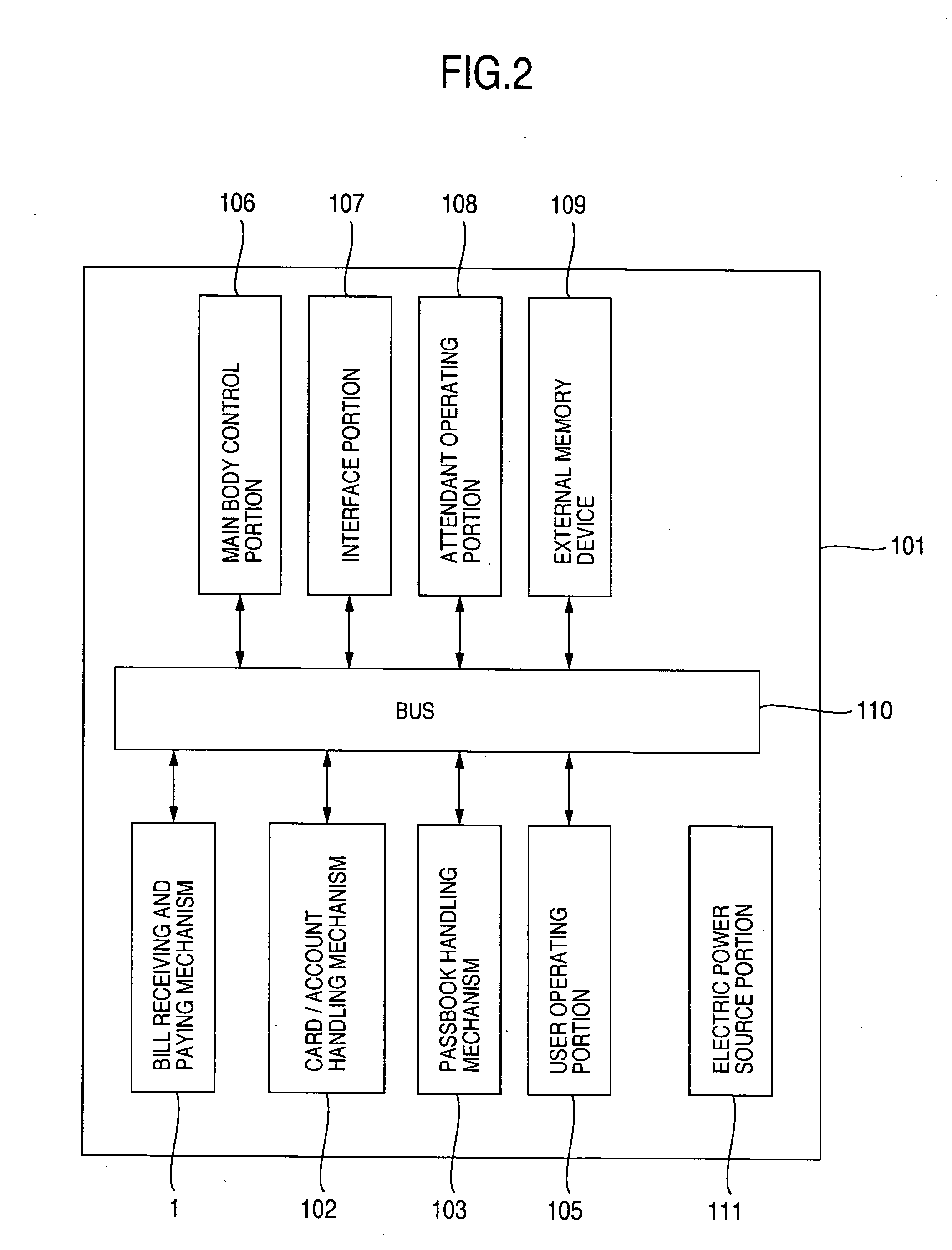
[0041]FIG. 2 is a block diagram showing a control relation of the automatic teller machine 101. The card / account handling mechanism 102, the passbook handling mechanism 103, the user operating porti...

embodiment 2

[0065] Next, a description will be given of a second embodiment in accordance with the present technique. In the second embodiment, as shown in FIGS. 19 and 20, a portion for delivering or accumulating the bills within the replenishment / retract cassette 6 is arranged in a rear face side of the apparatus. In addition, branching from the first carrying path connecting the temporary stacker 4 and the recycle cassette 5, a second carrying path connecting the branch point and the bill delivering and accumulating portion of the replenishment / retract cassette 6 is provided, and the second carrying path is structured such as to freely carry the bill in two-way direction.

[0066] As is known from the first embodiment, since the first carrying path (a part of the carrying path 8) connecting the temporary stacker 4 and the recycle cassette 5 carries the bill in the two-way direction, the carrying path structure of the entire of the apparatus is simple, and there is an effect that the jam genera...


PUM


Abstract

The invention provides a bill receiving and paying apparatus which has a function capable of replenishing and retracting the bill in correspondence to a lot of money kinds, secures the bill capacity without enlarging the apparatus, and has an improved maintenance characteristic and an improved operability. A recycle cassette per a money kind and a reject cassette are arranged in parallel in a depth direction as seen from a front face of a bill receiving and paying apparatus, a replenishment/retract cassette is arranged in a vertically laminated direction with respect to the recycle cassette and the reject cassette, the reject cassette is arranged in a front face side or a rear face side of the recycle cassette in correspondence to an operation and maintenance aspect of the apparatus. Further, a bill carrying path arranged in a front side of the replenishment/retract cassette is structured such as to be freely opened and closed, thereby being detachable from the front face side of the replenishment/retract cassette. Further, the bill receiving portion structured by the replenishment/retract cassette and the reject cassette, and the carrying path which may be freely opened and closed, are connected by one two-way carrying path.

Description

[0001] This application claims the benefit of priority of Japanese Application No. 2004-015118 filed on Jan. 23, 2004, the disclosure of which also is entirely incorporated herein by reference.BACKGROUND OF THE INVENTION [0002] The present invention relates to a bill receiving and paying apparatus, and more particularly to a technology for making it easy to add a recycle cassette and securing a bill capacity in correspondence to an increase of a kind of the received and paid bill without enlarging the apparatus. [0003] As a conventional bill receiving and paying apparatus, JP-A-2003-208654 discloses a bill receiving and paying apparatus comprising: [0004] a cash slot charging and receiving the bill; [0005] a validator validating the bill; [0006] a money classifying recycle cassette receiving the received bill and preparing for the next paying; [0007] a replenishment / retract cassette replenishing the bill in the money classifying recycle cassette in a lump or retracting the bill rece...

Claims


Application Information

Patent Timeline
IPC IPC(8): G07D9/00B07C5/00B65H3/44B65H5/26B65H85/00G07D7/00G07D11/00G07D13/00G07F7/04G07F9/00G07F19/00
CPCB65H2701/1912G07F19/205G07F19/20G07D11/0081G07D11/40
Inventor FUJITA, JUNJIKATOU, RIICHIKOSUGI, YASUTOMOTERAO, MASANORI
Owner HITACHI OMRON TERMINAL SOLUTIONS CORP
Why Eureka
Try Eureka