Apparatus for decomposing organic matter with radical treatment method using electric discharge

a technology of electric discharge and apparatus, which is applied in water/sewage treatment by oxidation, filtration separation, and separation processes, etc., can solve the problems of inability to decompose recalcitrant organic matter, harmful by-products of disinfection, and inability to achieve the effect of prolonging the life of generated radicals

Inactive Publication Date: 2005-09-01
KK TOSHIBA
View PDF5 Cites 46 Cited by
  • Summary
  • Abstract
  • Description
  • Claims
  • Application Information

AI Technical Summary

Benefits of technology

[0014] In accordance with an aspect of the present invention, there is provided an apparatus that can improve efficiency of organic matter decomposing treatment in a radical treatment apparatus using electric discharge.

Problems solved by technology

The by-products of disinfection are harmful to humans.
However, ozone cannot decompose recalcitrant organic matter like dioxins, agricultural chemicals, and endocrine-disruptors.
However, a technology that lengthens the lifetime of the generated radicals has not been established yet.
Accordingly, even if the radical treatment method by electric discharge is simply applied to water treatment, there is a problem in that the efficiency of the water treatment is not so high.

Method used


Image

  • Apparatus for decomposing organic matter with radical treatment method using electric discharge
  • Apparatus for decomposing organic matter with radical treatment method using electric discharge
  • Apparatus for decomposing organic matter with radical treatment method using electric discharge

Examples


tenth embodiment

(Tenth Embodiment)

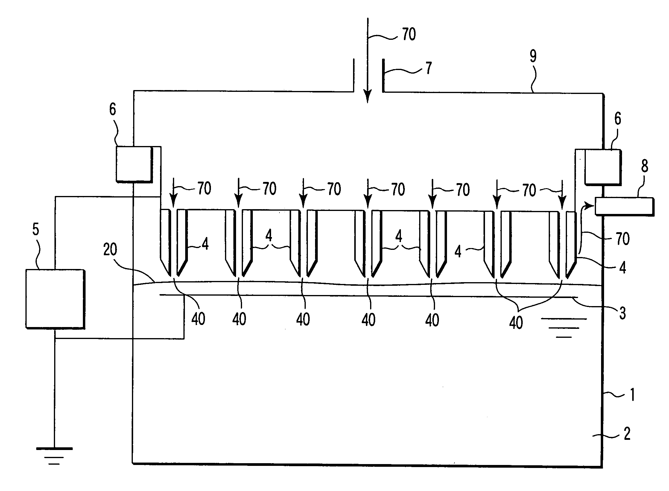
[0167]FIG. 11 is a diagram showing a configuration of a water treatment apparatus according to a tenth embodiment of the invention. In the tenth embodiment, the same configuration as the apparatus shown in FIGS. 1 and 10 is indicated by the same reference numerals, and the detailed description is neglected.

[0168] In the structure of the electrode unit according to the tenth embodiment, the needle-shaped electrode member that is arranged in a through-hole 120 forms the first electrode 4. The through-hole 120 is made in a glass member 12 that is arranged parallel to the second electrode 3. The first electrode 4 has the structure, in which the space between the needle-shaped electrode members is eliminated and the treatment water 2 does not enter the space. The through-hole 120 corresponds to the gas flow path 110 shown in FIG. 10, through which the gas 70 flows.

[0169] The functional effect of the third embodiment will be described below.

[0170] The gas 70 such as a...

eleventh embodiment

(Eleventh Embodiment)

[0173]FIG. 12 is a diagram showing a configuration of a water treatment apparatus according to an eleventh embodiment of the invention. In the eleventh embodiment, the same configuration as the apparatus shown in FIGS. 1 and 10 is indicated by the same reference numerals, and the detailed description is neglected.

[0174] In the apparatus of the eleventh embodiment, the electrode unit is provided in the lower chamber of the treatment water tank 1. The electrode unit includes the plurality of first electrodes 4 and the plate-shaped second electrode 3. The second electrode 3 constitutes the ground electrode, and is arranged in the treatment water 2. In the second electrode 3, the plurality of openings 30 are formed at the position opposite to the leading edges of the first electrodes 4 (electric discharge portions 40).

[0175] The first electrode 4 is formed by the needle-shaped electrode member to which the high voltage necessary to the electric discharge is applie...

twelfth embodiment

(Twelfth Embodiment)

[0181]FIG. 13 is a diagram showing a configuration of a water treatment apparatus according to a twelfth embodiment of the invention. In the twelfth embodiment, the same configuration as the apparatus shown in FIGS. 1 and 10 is indicated by the same reference numerals, and the detailed description is neglected.

[0182] In the apparatus of the twelfth embodiment, the electrode unit is provided in the lower chamber of the treatment water tank 1. The electrode unit includes the plurality of first electrodes 4 and the second electrode 3 having the metal mesh structure. The second electrode 3 constitutes the ground electrode, and is arranged in the treatment water 2. The second electrode 3 is arranged at the position opposite to the leading edge of the first electrode 4 (electric discharge portion 40).

[0183] The first electrode 4 is formed by the needle-shaped electrode member to which the high voltage necessary to the electric discharge is applied from the power supp...


PUM

PropertyMeasurementUnit
currentaaaaaaaaaa
voltageaaaaaaaaaa
distanceaaaaaaaaaa

Abstract

An apparatus performs radical treatment by electric discharge. The radical treatment apparatus includes an electrode unit having a gas flow path that blows gas onto treatment water and an electrode member that generates the electric discharge at a leading edge in order to generate a radical from the gas.

Description

CROSS-REFERENCE TO RELATED APPLICATIONS [0001] This application is based upon and claims the benefit of priority from prior Japanese Patent Applications No. 2004-026615, filed Feb. 3, 2004; No. 2004-075043, filed Mar. 16, 2004; No. 2004-121996, filed Apr. 16, 2004; and No. 2005-002932, filed Jan. 7, 2005, the entire contents of all of which are incorporated herein by reference. BACKGROUND OF THE INVENTION [0002] 1. Field of the Invention [0003] The present invention relates to an apparatus for water treatment using radical generated by electric discharge. [0004] 2. Description of the Related Art [0005] Recently, in addition to the water treatment method using chlorine, the water treatment method using the oxidation reaction of ozone (O3) is being applied. Both methods utilize the chemically strong oxidation power of an oxidant to decompose organic matter dissolved in the water. [0006] In oxidation power, ozone is as high as 2.07 electron volts while chlorine is 1.4 electron volts. W...

Claims


Application Information

Patent Timeline
Patent Type & Authority Applications(United States)
IPC IPC(8): B01J19/08C01B13/11C02F1/46C02F1/461C02F1/467C02F1/74
CPCB01J19/088C02F2305/023B01J2219/0828B01J2219/083B01J2219/0849B01J2219/0875C01B13/11C01B2201/14C01B2201/32C01B2201/64C01B2201/82C02F1/4608C02F1/4672C02F1/74C02F2001/46152C02F2101/305C02F2101/366C02F2201/46175C02F2201/4618C02F2201/4619B01J2219/0813
Inventor IIJIMA, TAKANORIMURATA, TAKAAKIKUBO, KIEOKITA, YUJIKOBAYASHI, SHINJIEBATA, TORU
Owner KK TOSHIBA
Why Eureka
Try Eureka