
Closure unit, mold for producing same, and dispenser-container incorporating a closure unit

Inactive Publication Date: 2005-09-01
ALBAAD MASSUOT YITZHAK
View PDF14 Cites 102 Cited by
  • Summary
  • Abstract
  • Description
  • Claims
  • Application Information

AI Technical Summary

Benefits of technology

[0013] By a lack of overlapping referred to above is meant that, dividing the closure unit into a plurality of imaginary elements along the upper surface of the unit, for example, such that each element, while being dimensionally small with respect to said upper surface, extends through the thickness of the unit up to the lower surface thereof in a preferably vertical direction, no such element will be substantially superposed over another such element. In some embodiments, a limited amount of overlapping in the vertical direction, between parts of the flap and the frame, may be possible due to the resilience of the material from which the closure unit is made. Such a material typically comprises a plastic, which can deform to a limited degree when force is applied. Thus, although the parts of the molds required for the molding of the overlapping portions also overlap, once cooled the closure unit can be removed from the mold by forcing a partial and temporary deformation of the overlapping parts to free these components from the molds.
[0034] The present invention is also directed to a dispenser-container for dispensing a plurality of tissues or the like sequentially, comprising a container having a dispensing opening for removing said tissues, and further comprising a closure unit according to the present invention, fixed to said container in overlaying relationship with respect to the opening, such that when the closure unit is in the open position the opening is accessible, and when the closure unit is closed the opening is substantially sealed, from an outside of said dispenser-container. By “sealed”, “sealingly” and so on, is meant that while a air tight or liquid tight closure is preferred, these terms also refer to any degree of closure between provided by the closure unit, in particular between the flap and the frame member, such that foreign matter is at least by an large prevented from entering the opening of the container, and at the same time, evaporation of fluids from the container is substantially slowed down during a typical life-cycle of a container.

Problems solved by technology

This however, is inconvenient and may even result in injury of the users fingers.
However, after repeated use, moisture from the tissues, and / or dirt or other foreign matter can adhere to the adhesive surface of the label, and severely reduce the adhesiveness thereof.
The tab overlies at least a substantial part of the body, requiring difficult and expensive injection molding techniques for its production, if at all available, resulting overall in an expensive dispenser.

Method used


Image

  • Closure unit, mold for producing same, and dispenser-container incorporating a closure unit
  • Closure unit, mold for producing same, and dispenser-container incorporating a closure unit
  • Closure unit, mold for producing same, and dispenser-container incorporating a closure unit

Examples


first embodiment

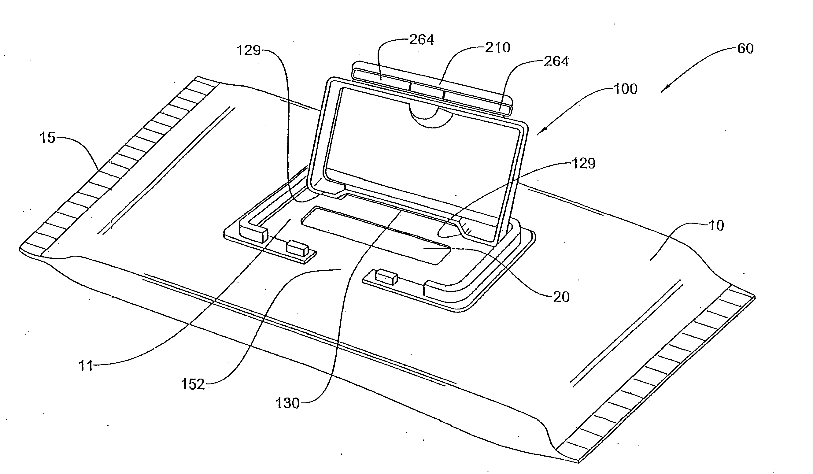
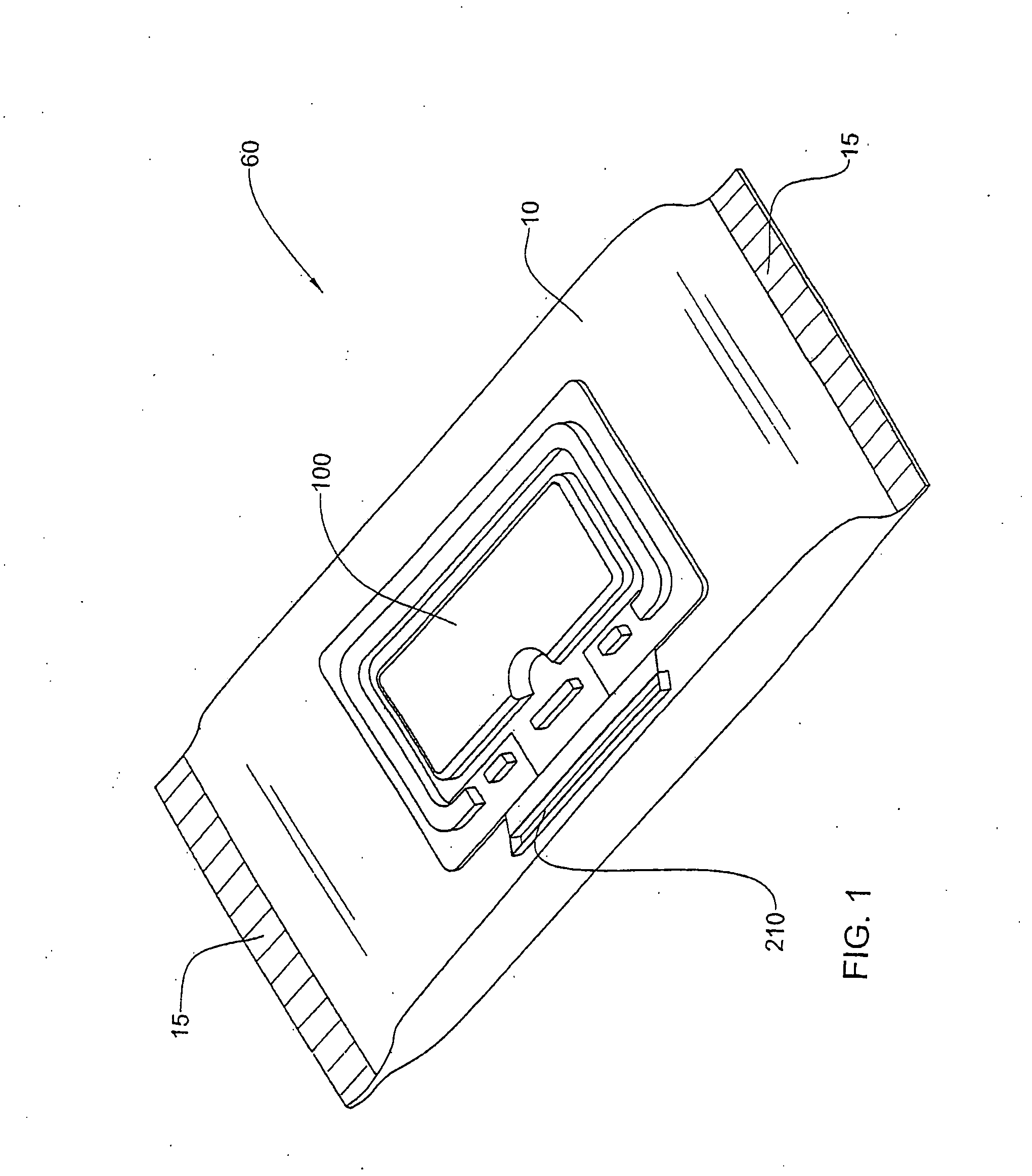
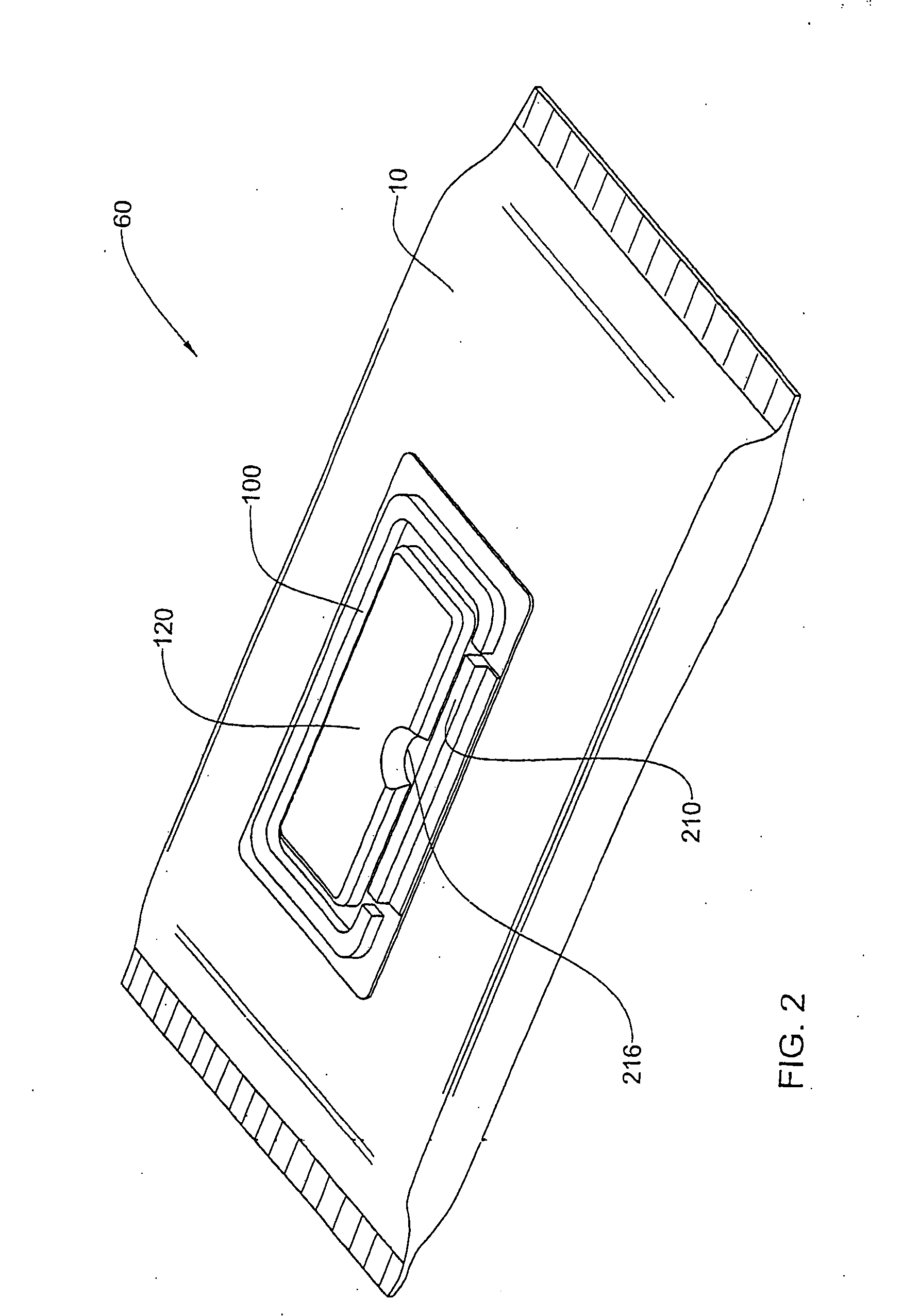
[0078] A typical dispenser-container according to the present invention is illustrated in FIGS. 1 to 3. The dispenser-container, generally designated 60, comprises a resealable container 10, which in the present embodiment may be similar to that of the conventionally known portable dispenser-container of a bag type for wet tissues. The container 10 is made from a flexible sheet suitably folded and bonded along a longitudinal join (not shown) and at ends 15 to provide an internal space that is filled with articles to be dispensed, such as tissues and the like.

[0079] The flexible sheet constituting the container 10 may comprise, for example, synthetic resins such as polyethylene, polypropylene, polyamide, polyester, and polyvinyl chloride in the form of a film, and the film may be a single layer or a laminated layer. The film may be a laminated layer of the above-mentioned film and an aluminum foil or paper, and the container 10 is in any case deformable.

[0080] The sheet constituting...

third embodiment

[0115] While the faces 411 and 429 are sloping at acute angles with respect to the surrounding frame 440, these angles with respect to a vertical datum are indeed very small, and thus the natural elasticity of the material from which the unit 400 is formed is sufficient to remove such a part when formed over suitable molds. Thus, by non-overlapping it is meant also to include embodiments such as the third embodiment, in which at least some parts may be disposed at an acute angle with respect to the frame, for example.

[0116] When formed as an integral unit, the flap 420 is joined to the frame 440 via a fracturable or otherwise separable break line 450, in the form of a “C”, excluding the hinge means 430. The break line 450 thus extends from one end of the pivot line of the hinge means 430, between the frame 440 and the border strip 428, and to the other end of the pivot line of the hinge means 430. The break line 450 may be perforated, or pre-weakened, or formed with substantially le...

seventh embodiment

[0166] The closure unit 700 of the seventh embodiment comprises a locking arrangement 780 for reversibly locking the flap 720 with respect to the frame 740 in a substantially sealing manner. The locking arrangement 780 according to this embodiment comprises the free leading edge 728 of the tab 725 and a complementary lip 785 comprised on the front part of the rib structure 750, the lip 785 projecting from the rib structure 750 in a rearwards direction towards the hinge arrangement 730. When it is desired to close the flap 720, this is rotated about the hinge arrangement 730, until the leading edge 728 is snapped into position below the lip 785. When it is desired to open the closure unit 700, the user presses the recess 722 in a direction towards the hinge arrangement 730. The resilience of the closure unit 700, and / or the play allowed for in the hinge arrangement 730, allow the leading edge 728 to be disengaged from the lip 785, and thus the flap 720 may be opened.

[0167] The closur...


PUM

PropertyMeasurementUnit
Angleaaaaaaaaaa
Angleaaaaaaaaaa
Thicknessaaaaaaaaaa

Abstract

A closure unit for selectively closing a package of wipes or the like is formed as an integral unit typically in or close to the closed position, and has a flap hinged with respect to a frame defining an opening for enabling dispensing of the wipes or the like therethrough. Break lines between the flap and the frame enable the flap to be torn from the frame at first use, and suitable positive locking means enable the flap to be reclosed with respect to the frame. The structure of the unit is such that no portion of the flap substantially overlaps any portion of the frame when the unit is initially formed, and thus then unit may be formed in or close to the closed position, particularly from sheet material.

Description

FIELD OF THE INVENTION [0001] This invention relates to a closure unit for use with a dispensing package, in particular such a package that is adapted for containing and dispensing articles, especially tissues or the like. BACKGROUND OF THE INVENTION [0002] Packages for articles such as tissues are well known in the art. Such articles may be supplied dry or soaked / impregnated in liquid or lotion e.g. a cleaning agent, a solvent, a skin treating preparation, etc. Most containers for such articles typically are in soft-pack form or in box form, i.e. in the shape of a parallelepiped or cylindrical (e.g. in the case of separably connected tissues in a reel). [0003] Typically, tissues have a generally rectangular shape and are supplied as separably connected sheets, or interleaved or inter folded discrete sheets stacked in a variety of different configurations, to facilitate the so-called pop-up effect, where each tissue has a leading portion that is first to pass through the opening, an...

Claims


Application Information

Patent Timeline
IPC IPC(8): A47K10/24B65D75/58B65D83/08B65D85/30B65D85/57B65D85/575B65H1/00
CPCB65D75/5838B65D83/0805B65D75/5877
Inventor CHASID, SHLOMITZAIDMAN, URI
Owner ALBAAD MASSUOT YITZHAK
Learn More