Trigger type fluid ejector
- Summary
- Abstract
- Description
- Claims
- Application Information
AI Technical Summary
Benefits of technology
Problems solved by technology
Method used
Image
Examples
first embodiment
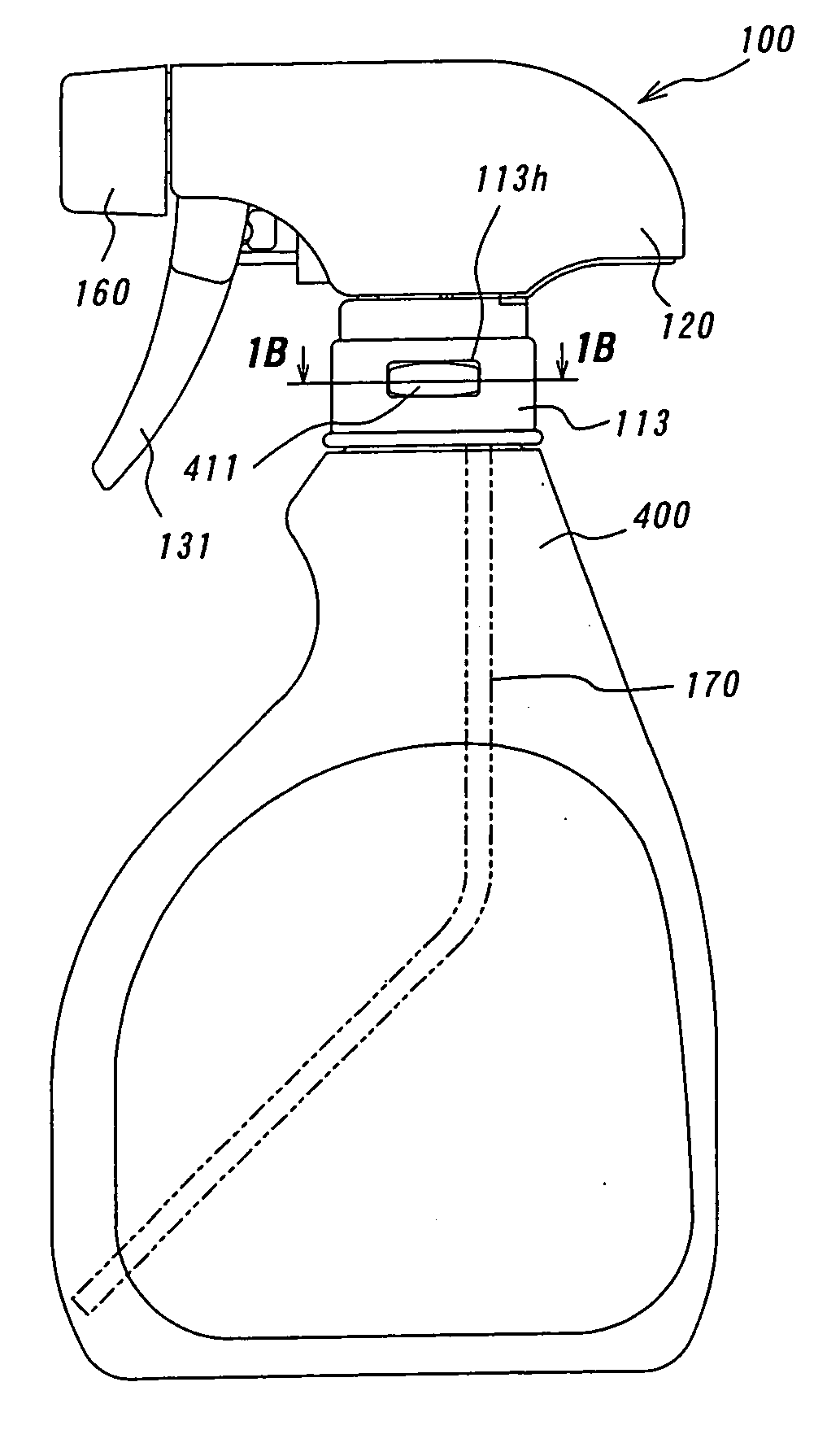
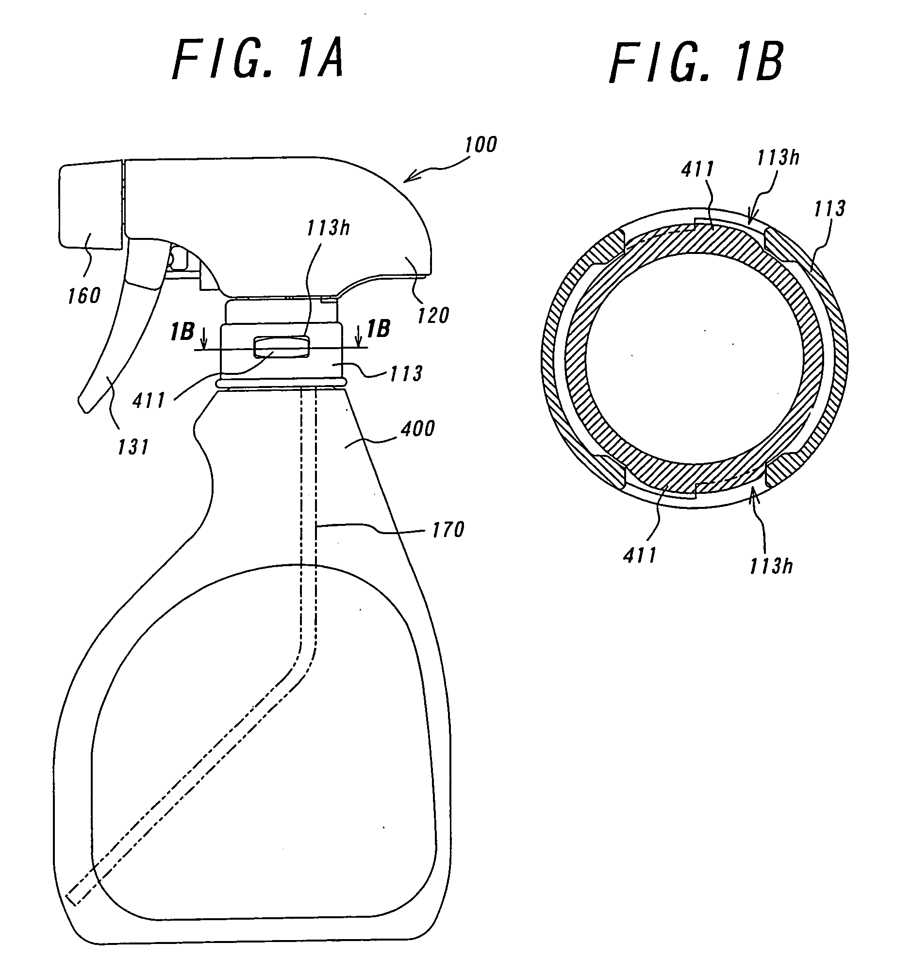
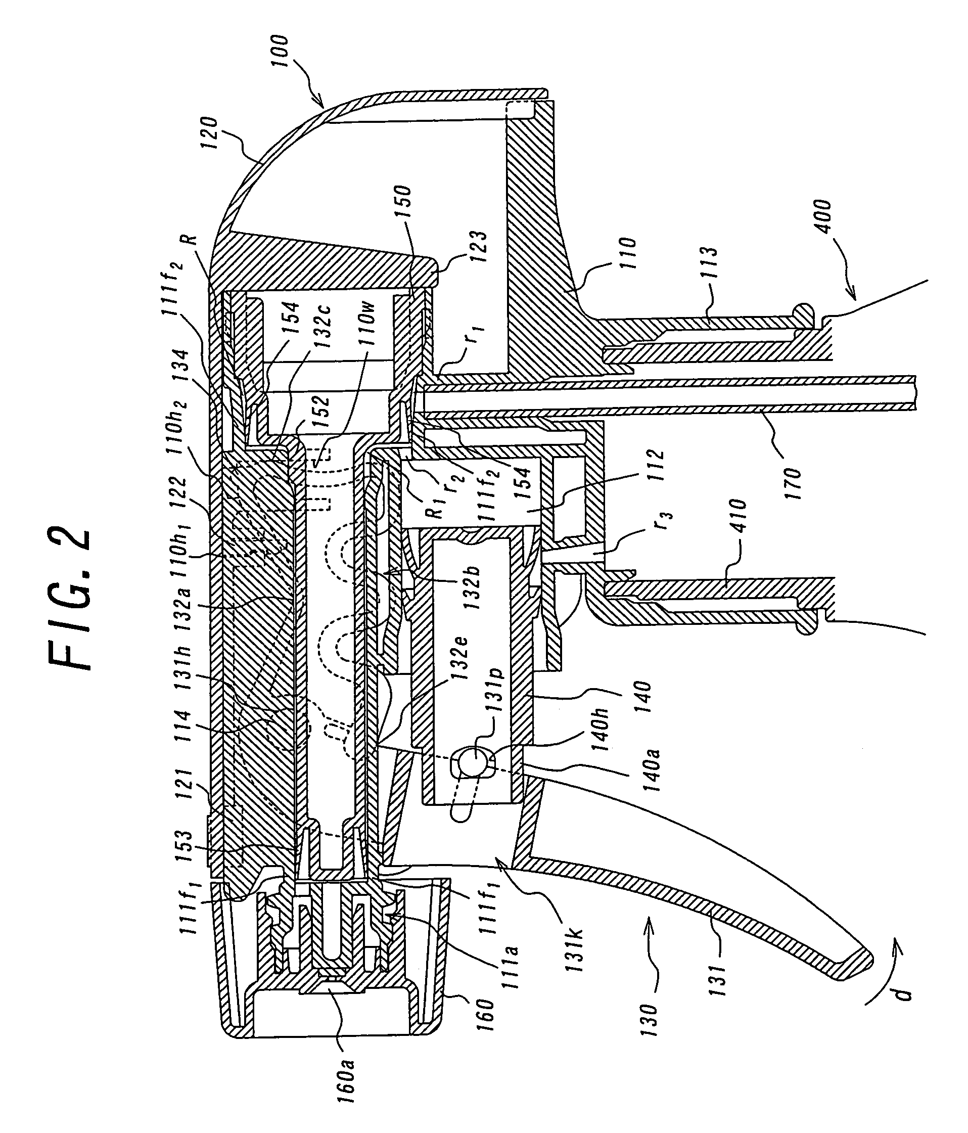
[0042]FIGS. 1A and 1B show a state in which a trigger pump 100 in accordance with a trigger type fluid dispenser of the present invention is installed to a vessel 400. The trigger pump 100 is composed of seven parts of a body 110, a cover 120, a trigger 130, a piston 140, a core element 150 integrally provided with a discharge valve and a suction valve, a nozzle 160, and a dip tube 170. As shown in FIGS. 3A and 3B, the body 110 integrally includes a discharge flow path 111 for discharging a fluid in the horizontal direction, a cylinder 112 disposed in parallel under the discharge flow path 111, and a connecting portion 113, described later. The discharge flow path 111 integrally has a spin element near a discharge port 111a thereof, and a rear end opening 111b thereof, which is a large-diameter portion forming a step portion, communicates with the dip tube 170 introduced through an opening in the connecting portion 113 via a first passage R1. The cylinder 112 communicates with the d...
second embodiment
[0068] Next, the operation of the vessel 400 fitted with the trigger pump 200 in accordance with the second embodiment will be described.
[0069] As shown in FIG. 10, first, the user pulls the hook portion 131 of the trigger 130 in the direction of arrow d, by which the piston 140 is pushed into the cylinder 212 against the elastic force of the elastic portion 132 of the trigger 130 in cooperation with the pulling operation of the trigger 131 to pressurize the interior of the enclosed space R1. At this time, the tip end 232e of the extension portion of the elastic member 132 presses the hook portion 131, and on the other hand, the bent portion 132a extends, and at the same time, the wavy portion 132b contracts.
[0070] As a result, the pressure in the enclosed space R1 increases. Therefore, the discharge valve 253 is separated from the seat portion 211f1 against the elastic force thereof while the suction valve 254 is kept seated. After the air in the enclosed space R1 is discharged fr...
third embodiment
[0073]FIG. 13 shows a state in which a trigger pump 300 in accordance with the present invention is installed to the vessel 400, and FIG. 14 is an exploded view of the trigger pump 300.
[0074] The trigger pump 300 includes a body 310, a cover 320, a trigger 330, a piston 340, a core element 350 forming a discharge valve and a suction valve, a nozzle 360, and a dip tube 370, and the core element 350 consists of three parts 351, 352 and 353. Therefore, in the third embodiment as well, as in the second embodiment, as parts except the body 310 and the core element 350, the parts common to those of the first embodiment are used, and the explanation of the common parts is omitted.
[0075] As shown in FIGS. 15A and 15B, the body 310 integrally includes a discharge flow path 311 for discharging a fluid in the horizontal direction, a cylinder 312 disposed in parallel under the discharge flow path 311, and a connecting portion 313. The discharge flow path 311 integrally has a spin element near ...
PUM
 Abstract
Description
Claims
Application Information
 - R&D
- Intellectual Property
- Life Sciences
- Materials
- Tech Scout
- Unparalleled Data Quality
- Higher Quality Content
- 60% Fewer Hallucinations
Browse by: Latest US Patents, China's latest patents, Technical Efficacy Thesaurus, Application Domain, Technology Topic, Popular Technical Reports.
© 2025 PatSnap. All rights reserved.Legal|Privacy policy|Modern Slavery Act Transparency Statement|Sitemap|About US| Contact US: help@patsnap.com


