Low-loss transmission line structure

a transmission line and low-loss technology, applied in the direction of waveguides, waveguide type devices, high-frequency circuit adaptations, etc., can solve the problems of limited use of high-frequency microstrip transmission lines and insufficient use of traditional microstrip transmission lines at such high frequencies

Inactive Publication Date: 2005-09-01
LUCENT TECH INC
View PDF8 Cites 27 Cited by
  • Summary
  • Abstract
  • Description
  • Claims
  • Application Information

AI Technical Summary

Benefits of technology

[0004] The present inventor has realized that the aforementioned RF signal loss at higher frequencies is caused to a large extent by the electromagnetic field in the dielectric substrate underlying the transmission line that results as a signal propagates along the transmission line. At higher frequencies, the degree of substrate interaction per unit length increases, resulting in the aforementioned weak signal at the intended destination of the signal.

Problems solved by technology

However, while transmission lines of this type provide a high-quality signal path at such frequencies, they are limited in their usefulness at higher frequencies, such as at or above 70 GHz.
Thus, traditional microstrip transmission lines are inadequate for use at such high frequencies.

Method used


Image

  • Low-loss transmission line structure
  • Low-loss transmission line structure
  • Low-loss transmission line structure

Examples


Embodiment Construction

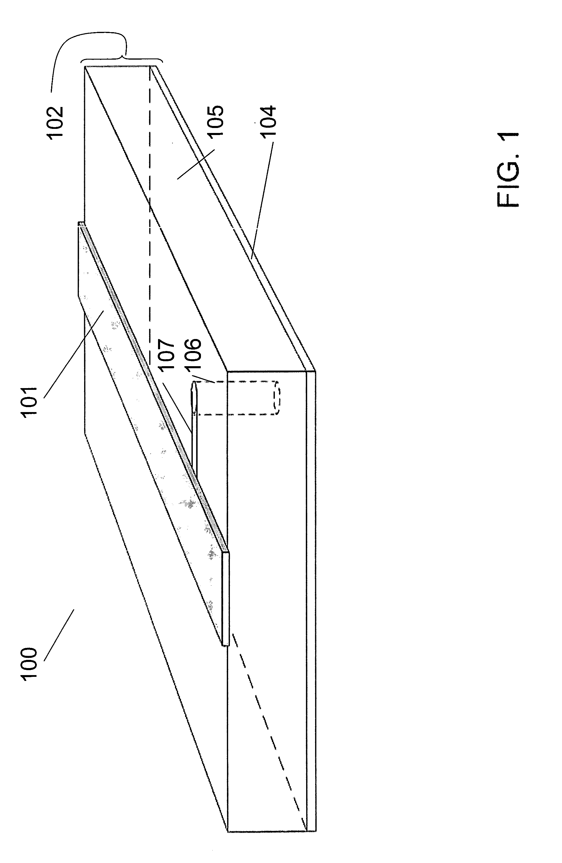
[0011]FIG. 1 shows an illustrative prior art transmission line structure 100 having substrate 102 that is, illustratively, a multi-layered circuit board having a dielectric layer 105 and a metallized ground plane layer 104. The metallized layer 104 is, illustratively, a thin layer of copper material. The dielectric layer 105 could be for example, a layer of silicon dioxide material. Transmission line 101 is, illustratively, connected to ground plane 104 by lead 107 connected to via 106. Vias such as via 106 are well known in the art and are, illustratively, metallized holes through the dielectric layer 105 that provide a conducting electrical path to ground layer 104.

[0012] While the illustrative transmission line of FIG. 1 is useful as a path for routing RF signals across circuit boards in many applications, problems result as the frequency of the RF signal rises. In particular, as the frequency of the signal increases, that signal is more easily attenuated by the well-known elect...


PUM


Abstract

A microstrip transmission line structure is disclosed wherein a transmission element is attached to a substrate in a way such that the element is suspended above the substrate separated by a predetermined distance from a ground plane. In one embodiment, the transmission element is supported by a plurality of support legs that are disposed in a way such that the transmission element is suspended above the substrate. In another embodiment, a portion of the substrate is removed in a way such that, when the transmission element is disposed on the substrate, the line is separated from the ground plane by a predetermined distance.

Description

FIELD OF THE INVENTION [0001] The present invention relates to high frequency electronic circuit boards and, more particularly, to low-loss transmission lines in such circuit boards. BACKGROUND OF THE INVENTION [0002] Efficient transmission of broadband radio frequency (RF) signals is essential to meet the demanding requirements of high-speed networking systems. Individual circuit elements, such as 50 Ohm impedance microstrip transmission lines, which are very well known in the art, must be carefully designed to minimize signal losses. The importance of minimizing these losses is increasing as such systems operate at higher frequencies over longer distances. Various well-known transmission lines, such as the aforementioned microstrip transmission lines, have been used to carry signals on multilayered circuit boards for relatively low frequency applications, such as at or below 40 GHz. [0003] However, while transmission lines of this type provide a high-quality signal path at such fr...

Claims


Application Information

Patent Timeline
Patent Type & Authority Applications(United States)
IPC IPC(8): H01P3/08H05K1/02
CPCH01P3/081H05K2201/0394H05K1/024H01P3/084
Inventor METZ, CARSTEN
Owner LUCENT TECH INC
Why Eureka
Try Eureka