Front plate and display device using same

a display device and front plate technology, applied in the field of display devices, can solve the problems of difficulty in combining prior art techniques with display panels, display which has a low light output efficiency, and common problems such as the attenuation of even emitted light from light emitting elements, and achieve the effect of improving image quality

Inactive Publication Date: 2005-09-01
HITACHI LTD
View PDF7 Cites 33 Cited by
  • Summary
  • Abstract
  • Description
  • Claims
  • Application Information

AI Technical Summary

Benefits of technology

[0029] According to the present invention, the image quality can be improved.

Problems solved by technology

However, the prior art improving means for reducing the transmittance to improve the bright-room contrast has a problem of reducing the output light by the transmittance τ as well, so that the exit light must be previously increased.
In some cases, difficulties are encountered in combining the prior art technique with a display panel which originally has a low output luminance or a display which has a low light output efficiency.
In either case, there is no difference in the function of improving the bright-room contrast by adjusting the transmittance, but a common problem still remains unsolved in regard to the attenuation of even emitted light from light emitting elements.
However, the application of this technique to a display device gives rise to some concerns as mentioned below.

Method used


Image

  • Front plate and display device using same
  • Front plate and display device using same
  • Front plate and display device using same

Examples


first embodiment

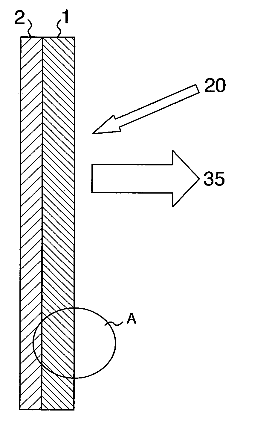
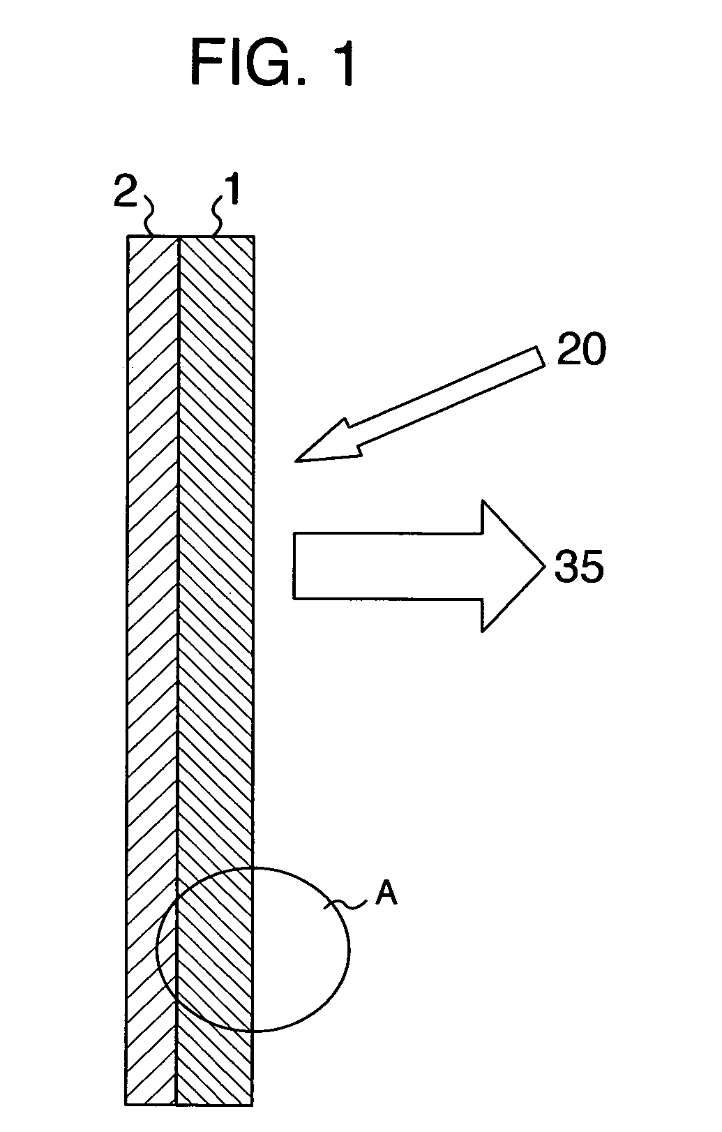
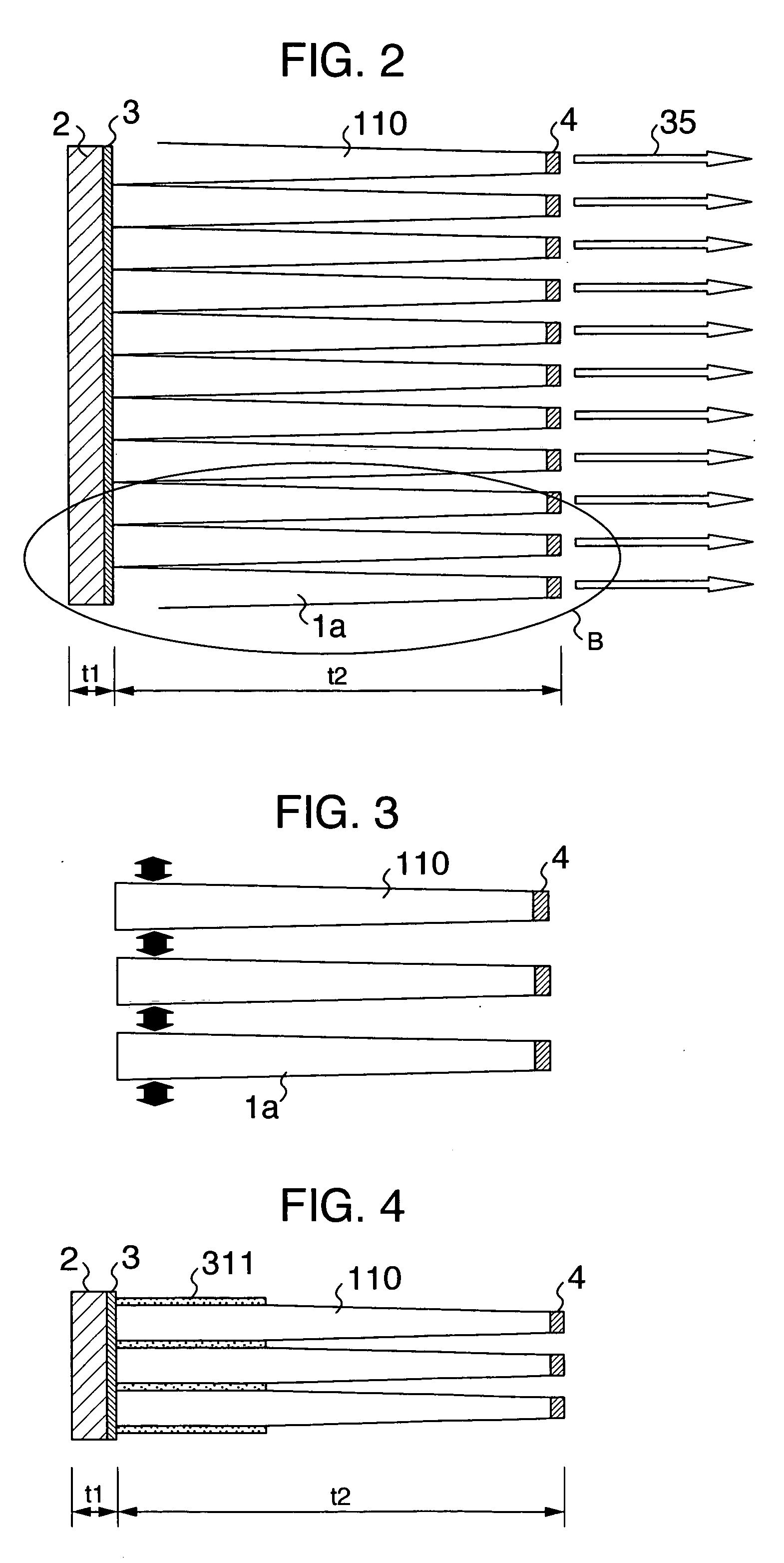
[0049]FIG. 2 is a schematic diagram generally showing, in an enlarged view, a portion A of the needle-shaped optical sheet in FIG. 1, which is the front plate according to a FIG. 3 shows frustrum-shaped protrusions which are individual elements of the needle-shaped optical sheet, depicting that they are bundled at the roots. FIG. 4 is an enlarged schematic diagram of a portion B in FIG. 2. This embodiment employs, as the frustrum-shaped protrusions, tapered frusto-conical fibers 1a, the diameter of which is different at both ends thereof. The tapered frusto-conical fibers 1a are bundled together.

[0050] In FIGS. 2, 3, 4, the frusto-conical fibers 1a are used as needle-shaped light guide paths 110 for guiding light from the display panel 2. The end faces having a larger diameter (thickness) of the frusto-conical fibers 1a are fixed by a black adhesive layer 311 or the like near the display panel 2, and implanted on the display panel 2 through a transparent adhesive layer 3 to make th...

third embodiment

[0069]FIG. 9 shows needle-shaped light guide paths of a front plate according to a As illustrated in FIG. 9, unlike FIG. 8, the concave groove 7 is not filled with the light absorbent 6, but instead, a light absorbing film 5 for absorbing light is disposed to cover the surface of the needle-shaped light guide paths 110, except for the diffusion surface 4 at the leading end of the protrusion, thereby reducing the reflectivity.

[0070] External light 20 incident into the concave groove 7 is absorbed by the light absorbing film 5 formed on the surface of the needle-shaped light guide paths 110 and attenuated, as shown in FIG. 9, as it repeats reflections. In this way, the bright-room contrast is further improved as compared with the first embodiment.

[0071] In this embodiment, when the frusto-conical fibers undergo surface processing, before they are bundled, for bundling them, optical processing can be implemented irrespective of the manufacturing method, thus increasing the degree of ...


PUM

PropertyMeasurementUnit
aspect ratioaaaaaaaaaa
cross-sectional areaaaaaaaaaaa
areaaaaaaaaaaa

Abstract

Frusto-conical needle-shaped light guide paths are implanted on the surface of a display panel such that output light from display elements propagate through the needle-shaped light guide paths through total reflection, while external light repeats reflections multiple times on wedge-shaped surfaces of the light guide paths, and attenuates. A light absorbing film is coated on the surfaces of he needle-shaped light guide paths to increase a contrast ratio. Thus, a higher contrast can be accomplished in a bright room, and cross-talk between adjacent pixels is reduced, and a reduction in contrast due to display light is also alleviated by employing longer implanted needle-shaped light guide paths, and bringing light incident surfaces of the needle-shaped light guide paths into close contact with the surface of the display panel.

Description

INCORPORATION BY REFERENCE [0001] The present application claims priority from Japanese application JP2004-031504 filed on Feb. 9, 2004, the content of which is hereby incorporated by reference into this application. BACKGROUND OF THE INVENTION [0002] 1. Field of the Invention [0003] The present invention relates to a display device which mitigates reduced contrast (bright-room contrast) due to external light when a display screen is viewed in a bright room in order to reduce blurred images, and more particularly, to a front plate which is integrally or separately arranged on a front surface of the display device to improve the contrast of viewed images, and a display device using the same. [0004] 2. Description of the Related Art [0005] Conventionally, for improving the contrast in a bright room (hereinafter called the “bright-room contrast) of a display device using a display panel having selfluminous pixels, arranged in matrix, which emit light in accordance with the Lambert dist...

Claims


Application Information

Patent Timeline
Patent Type & Authority Applications(United States)
IPC IPC(8): F21V8/00G02B1/10G02B5/02G02B27/00G02F1/1335G09F9/00
CPCG02B27/0018G02B6/0001
Inventor OHSAWA, MICHITAKA
Owner HITACHI LTD
Why Eureka
Try Eureka