Light reflector

a light reflector and reflector technology, applied in the field of light reflectors, can solve the problems of reflector yellowing, illuminance drop after, source yellowing, etc., and achieve the effect of reducing illuminance drop

Inactive Publication Date: 2005-09-01
YUPO CORP
View PDF6 Cites 23 Cited by
  • Summary
  • Abstract
  • Description
  • Claims
  • Application Information

AI Technical Summary

Benefits of technology

[0008] An object of the present invention is to provide a light reflector which has a reduced illuminance drop and causes no uneven illuminance in the surface direction due to deflection during use (which is a defect of an olefin-based resin film). The present invention is an improvement over the light reflector made of a polyester which has heretofore been used.
[0009] The present inventors found that the aforesaid problems can be solved by a light reflector obtained by the lamination of an olefin-based resin film containing a filler to be used for the area that is provided with a long-range stable light-reflecting capacity and a specific substrate to be used for the area that is provided with a rigidity high enough to cause no deflection. With this combination, the present invention has thus been developed.

Problems solved by technology

However, there was a case where the light reflector in the vicinity of the light source undergoes yellowing due to deterioration by heat generated by the light source and light having a wavelength mainly in the vicinity of ultraviolet range and this light reflector yellowing gives an illuminance drop after an extended period of time.
Further, in the case where a relatively soft light pipe is used, the contact with the light reflector often causes flaws on the light pipe.
However, the olefin-based thermoplastic resin film has the disadvantage that it lacks rigidity and can be easily deformed to undergo deflection or strain as compared with polyester film, making it impossible to obtain reflected light which is uniform in the surface direction and hence causing the occurrence of uneven illuminance.

Method used


Image

  • Light reflector
  • Light reflector

Examples


production example 1

[0130] A composition (a) obtained by mixing PP1 and HDPE as olefin-based resin and barium sulfate and titanium dioxide as filler in a proportion set forth in Table 2 and a composition (g) obtained by mixing PP2 as olefin-based resin and calcium carbonate 1 and titanium dioxide as filler in a proportion set forth in Table 2 were melted and kneaded at 250° C. using one extruder and two separate extruders, respectively.

[0131] These kneaded materials were fed into a co-extrusion die the temperature of which had been set at 250° C. where they were then laminated in such an arrangement that the composition (a) was an interlayer (A) and the composition (g) was laminated on the interlayer (A) as a surface layer (B) and a back layer (C), respectively. Thereafter, the laminate was extruded to form a film which was then cooled over a cooling roll to about 60° C. to obtain an unstretched laminate (B / A / C).

[0132] This laminate was heated to 145° C., stretched by a factor of 8 longitudinally by ...

production example 2

[0133] A composition (b) obtained by mixing PP1 and HDPE as olefin-based resin and barium sulfate and titanium dioxide as filler in a proportion set forth in Table 2 and a composition (i) obtained by mixing PP2 as olefin-based resin and calcium carbonate 2 and titanium dioxide as filler in a proportion set forth in Table 2 were melted and kneaded at 250° C. using separate extruders.

[0134] A monoaxially-stretched three-layer film 1 having a thickness of 100 μm (B / A / C=0.5 μm / 99 μm / 0.5 μm) was obtained in the same manner as in Production Example 1 except that the extrusion rate of these kneaded materials was changed.

production example 3

[0135] A monoaxially-stretched three-layer film 1 having a thickness of 180 μm (B / A / C=0.5 μm / 179 μm / 0.5 μm) was obtained in the same manner as in Production Example 2 except that the extrusion rate of the various compositions was changed.


PUM

PropertyMeasurementUnit
total ray reflectanceaaaaaaaaaa
foaming ratioaaaaaaaaaa
porosityaaaaaaaaaa

Abstract

An object of the present invention is to provide a light reflector, which causes no unevenness in luminance in the surface direction due to deflection in use. The present invention is a light reflector comprising: an olefin-based resin film 1 comprising a filler and having a total ray reflectance of 90% or more, which is stretched at least monoaxially at an area stretch ratio of from 1.5 to 80; and at least one of the following substrates (1) to (4): (1) Film 2 comprising at least one of olefin-based resin and polyester-based resin as a main component; (2) Woven cloth 3 or non-woven cloth 4; (3) Metal plate 5; and (4) Molded material 6 comprising a thermoplastic resin composition (a1) containing a foaming agent and having a foaming ratio of from 1.05 to 10 as calculated by the following equation (1): Foaming ratio=ρo / ρ  (1) where ρo represents the density before foaming; and ρ represents the density after foaming.

Description

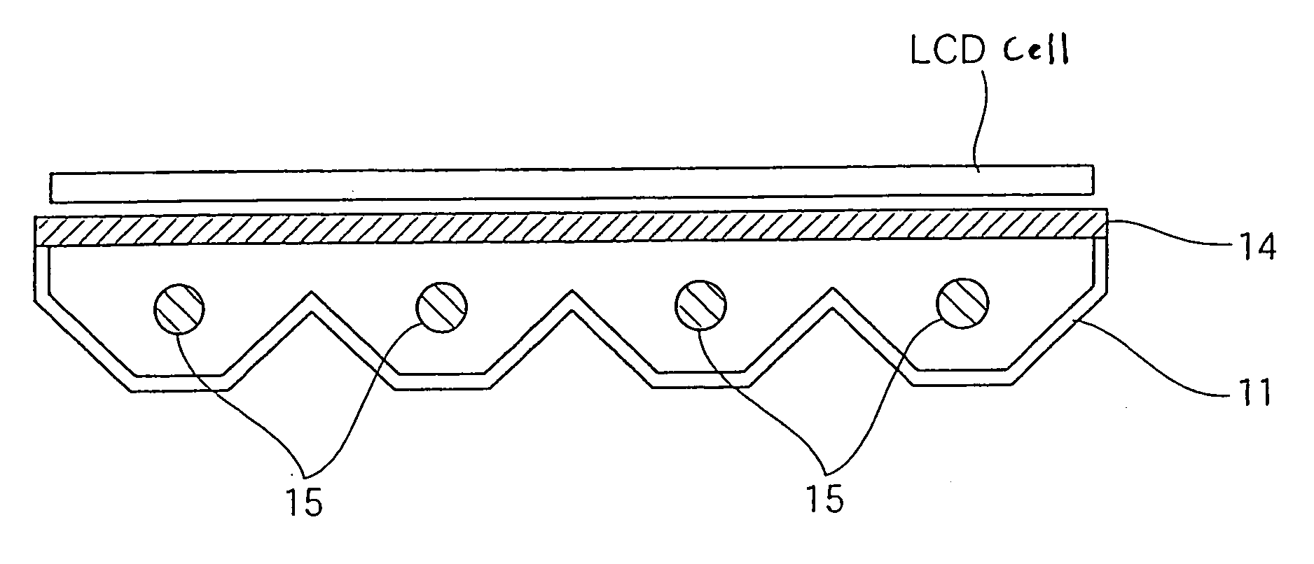
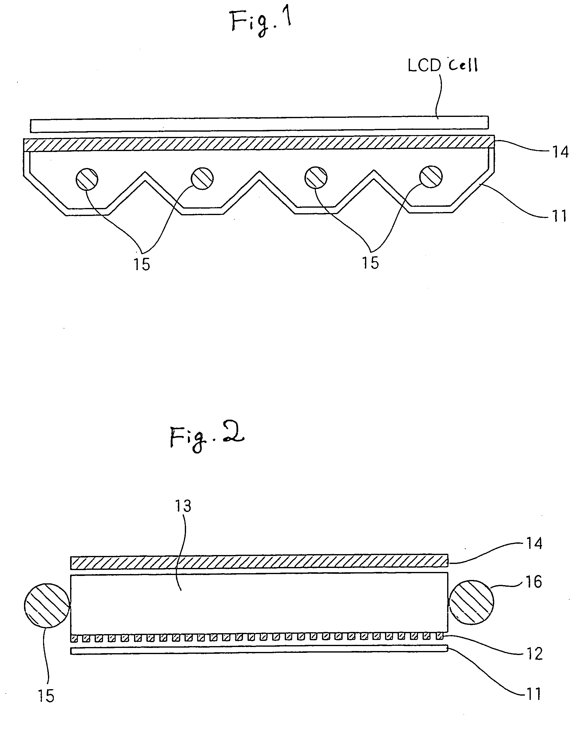
TECHNICAL FIELD [0001] The present invention relates to a light reflector which reflects light from a light source such as a fluorescent lamp in a backlight type area light source device. These devices have shown a trend for increase in size and for a light reflector which has a rigidity high enough to cause no unevenness in luminance in the surface direction due to deflection in use. BACKGROUND ART [0002] In recent years, backlight type liquid crystal displays with a built-in light source and decorative illumination panels for printed matter have been widely distributed. Among backlight type built-in area light sources (hereinafter referred to as “backlight unit”), the configuration of side light type light source comprises a light pipe 13 having a halftone printed on a transparent acryl plate, a light reflector 11 disposed on one surface of the light pipe 13, a diffuser panel 14 disposed on the other surface of the light pipe 13 and a cold cathode lamp 15 (optionally 16) disposed ...

Claims


Application Information

Patent Timeline
Patent Type & Authority Applications(United States)
IPC IPC(8): B32B1/00B32B27/00G02B1/10G02B5/08
CPCB32B27/00G02B5/0808Y10T428/24355B32B1/00G02B5/0841B32B15/085B32B5/024B32B5/022B32B27/365B32B27/32B32B27/20B32B7/12B32B27/12B32B27/08
Inventor TAKAHASHI, TOMOTSUGUUEDA, TAKAHIKOKOYAMA, HIROSHIOHKAWACHI, ICHIRO
Owner YUPO CORP
Why Eureka
Try Eureka