Truing method and apparatus

a technology of truing apparatus and truing machine, which is applied in the direction of grinding machine components, manufacturing tools, and abrasive surface conditioning devices, etc., can solve the problems of increasing the cost of truing apparatus, increasing the heat generation of truing apparatus, and enlarge the grinding machine, so as to reduce the truing apparatus and reduce the heat generation. , the effect of reducing the truing apparatus

Inactive Publication Date: 2005-09-01
TOYODA MASCH WORKS LTD
View PDF5 Cites 5 Cited by
  • Summary
  • Abstract
  • Description
  • Claims
  • Application Information

AI Technical Summary

Benefits of technology

[0010] With this construction, inference is made to determine the truing shape from which the grinding surface having been trued with the grinding wheel being rotated at the low rotational speed during the truing operation is deformed to the desired shape due to the centrifugal expansion depending on the rotational speed difference when the grinding wheel is rotated at the high rotational speed during the grinding operation. Then, the grinding surface of the grinding wheel being rotated at the lower rotational speed is trued with the truing roll to the inferred truing shape. Thus, according to the truing method, the rotational speed of a rotational spindle with the truing roll mounted thereon can be set to be low. This advantageously makes it possible to downsize the truing apparatus or to mount the truing roll on the work spindle coaxially. Further, since the rotational spindle with the truing roll mounted thereon does not need to be rotated at a high speed, heat generation which would otherwise result from the high speed rotation of the truing roll can be suppressed to prevent the work head and a bed from being thermally displaced due to the conduction of heat thereto, so that the machining accuracy can be improved. In addition, according to the truing apparatus, it can be realized to true the grinding surface of the grinding wheel being rotated at the low rotational speed, with the truing roll being rotated at the low rotational speed so that the trued grinding surface becomes the desired shape when the grinding wheel is then rotated at the high rotational speed for the grinding operation for example. Therefore, it can be realized to provide the truing apparatus which is less in heat generation and precise.

Problems solved by technology

However, this truing apparatus is required to rotate the rotational spindle at such a high speed and gives rise to a problem that the apparatus becomes a large scale to increase the cost.
Further, since the grinding wheel has to be retracted through a long distance at the time of a truing operation, the moving stroke of the grinding wheel is elongated thereby to enlarge the grinding machine.
In addition, the high speed rotation of the rotational spindle causes the truing apparatus to increase heat generation, and such heat is conducted to the work head and the bed.
As a consequence, a thermal displacement is brought about, e.g., between the axis of the rotational spindle with the truing roll mounted thereon and the axis of the work spindle, so that an error may be involved in the distance between the grinding wheel surface which has to be trued with the truing roll and the axis of the work spindle.

Method used


Image

  • Truing method and apparatus
  • Truing method and apparatus
  • Truing method and apparatus

Examples


Embodiment Construction

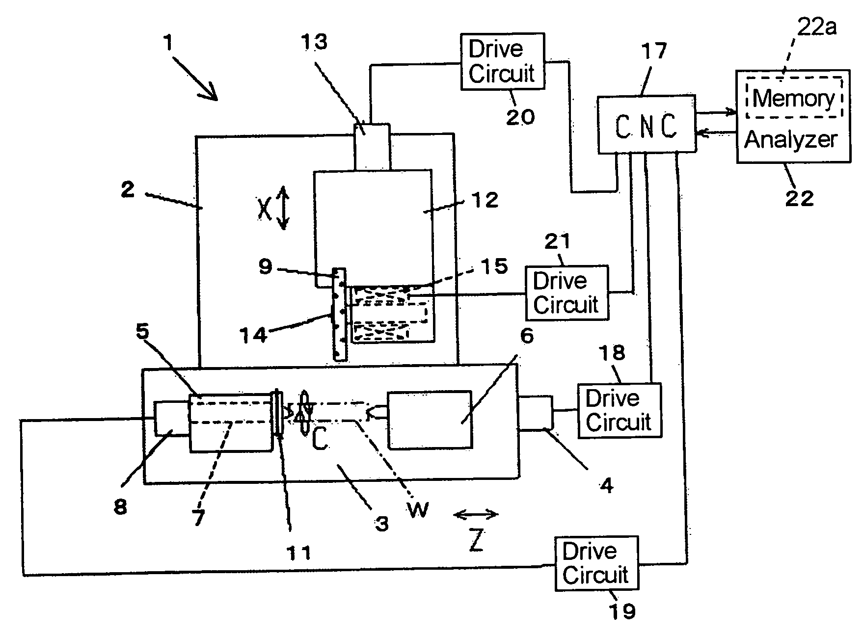
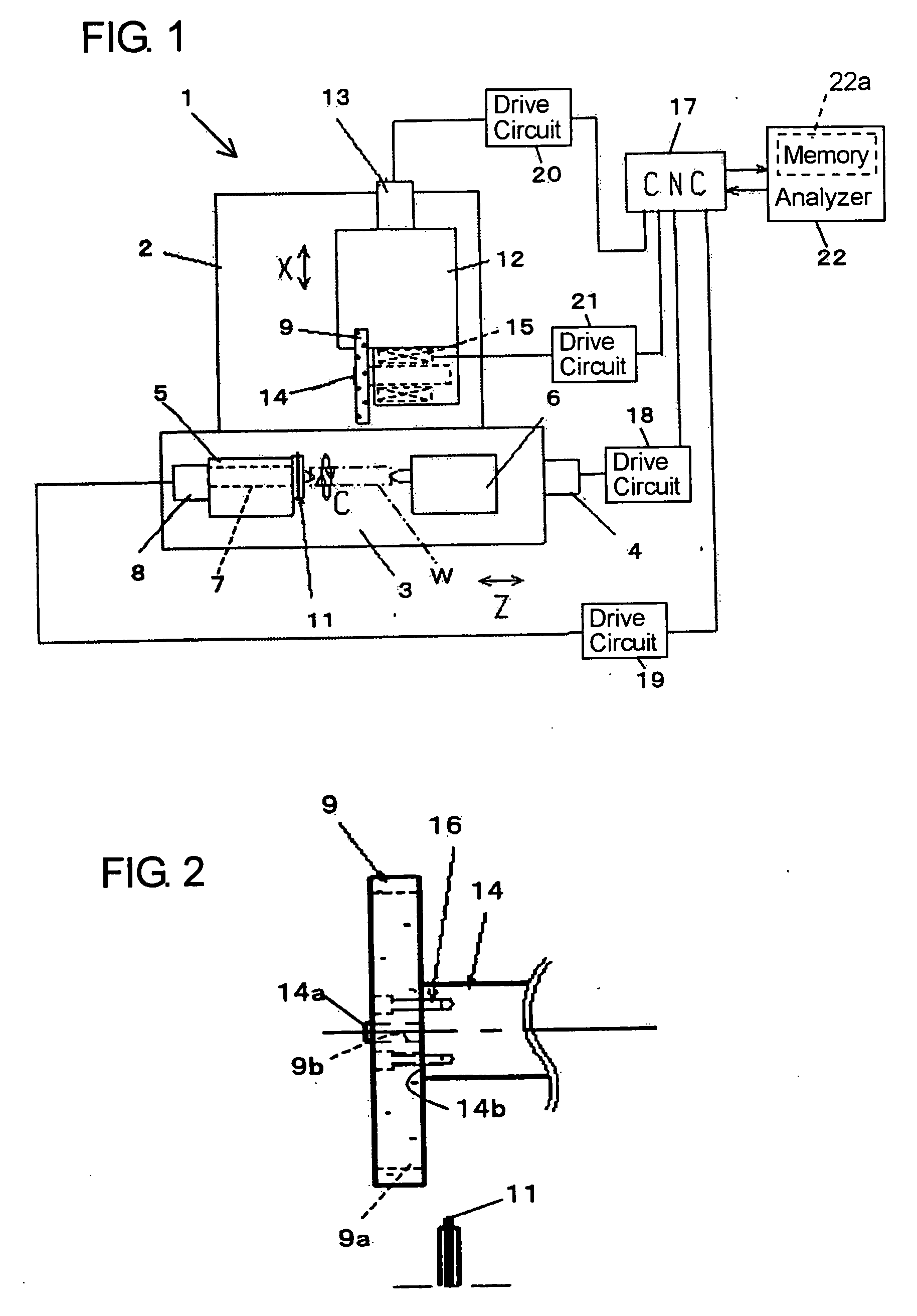
[0016] Hereinafter, an embodiment in a truing method and apparatus according to the present invention will be described in detail with reference to the accompanying drawings. Referring now to FIG. 1, a table 3 is slidably mounted on a bed 2 of a grinding machine 1 and is movable by a servo motor 4 through a ball screw (not shown) in a Z-axis direction. A work head 5 and a foot stock 6 are mounted on the table 3 to face with each other, and a workpiece W is sustained by means of centers (not shown) between the work head 5 and the foot stock 6 in the Z-axis direction. A work spindle 7 is rotatably carried on the work head 5 to be rotationally driven by a servo motor 8. The workpiece W is kept in a drive connection with the work spindle 7 by means of a drive member (not shown) and is rotationally driven together with the work spindle 7. A truing roll 11 for truing a grinding wheel 9 referred to later is coaxially secured to an extreme end portion of the work spindle 7.

[0017] On the be...


PUM

PropertyMeasurementUnit
diameteraaaaaaaaaa
rotational speedaaaaaaaaaa

Abstract

In a truing method and apparatus, an analyzing method is employed to calculate a truing shape from which a grinding surface having been trued with a grinding wheel being rotated at a low rotational speed during a truing operation is deformed to a desired shape due to centrifugal expansion depending on a rotational speed difference when the grinding wheel is rotated at a high rotational speed during a grinding operation. Then, with the grinding wheel being rotated at the low rotational speed, the grinding surface is trued with a truing roll to the calculated truing shape. As a result, the grinding surface of the grinding wheel being rotated at the low rotational speed is trued with the truing roll taking into consideration the centrifugal expansion of the grinding surface which takes place when the grinding wheel is rotatated at the high rotational speed during the grinding operation subsequent to the truing operation.

Description

[0001] This application claims priority under 35 U.S.C. 119 with respect to Japanese Application No. 2004-056685 filed on Mar. 1, 2004. BACKGROUND OF THE INVENTION [0002] 1. Field of the Invention [0003] The present invention relates to a truing method and apparatus for truing a grinding surface of a grinding wheel with a truing roll being rotationally driven. [0004] 2. Discussion of the Related Art [0005] Japanese Patent No. 2749154 describes a truing apparatus for a grinding machine in which a rotating grinding wheel and a rotating workpiece are relatively moved to grind the workpiece with the grinding wheel. In the grinding machine, a work spindle is rotatably supported on a work head for supporting the workpiece, a chuck device for gripping the workpiece and a truing roll for truing the grinding wheel are in turn fixed on an extreme end of the work spindle in alignment, and the grinding wheel and the work head are moved relatively in two directions orthogonal to each other to tr...

Claims


Application Information

Patent Timeline
Patent Type & Authority Applications(United States)
IPC IPC(8): B24B53/00B24B49/16B24B53/08
CPCB24B53/08B24B49/16
Inventor YORITSUNE, MASASHIWAKAZONO, YOSHIOKOBAYASHI, HISANOBU
Owner TOYODA MASCH WORKS LTD
Why Eureka
Try Eureka