
Wireless charging receiving apparatus, method for realizing wireless charging, and mobile terminal

Active Publication Date: 2021-02-11
ZTE CORP
View PDF0 Cites 1 Cited by
  • Summary
  • Abstract
  • Description
  • Claims
  • Application Information

AI Technical Summary

Benefits of technology

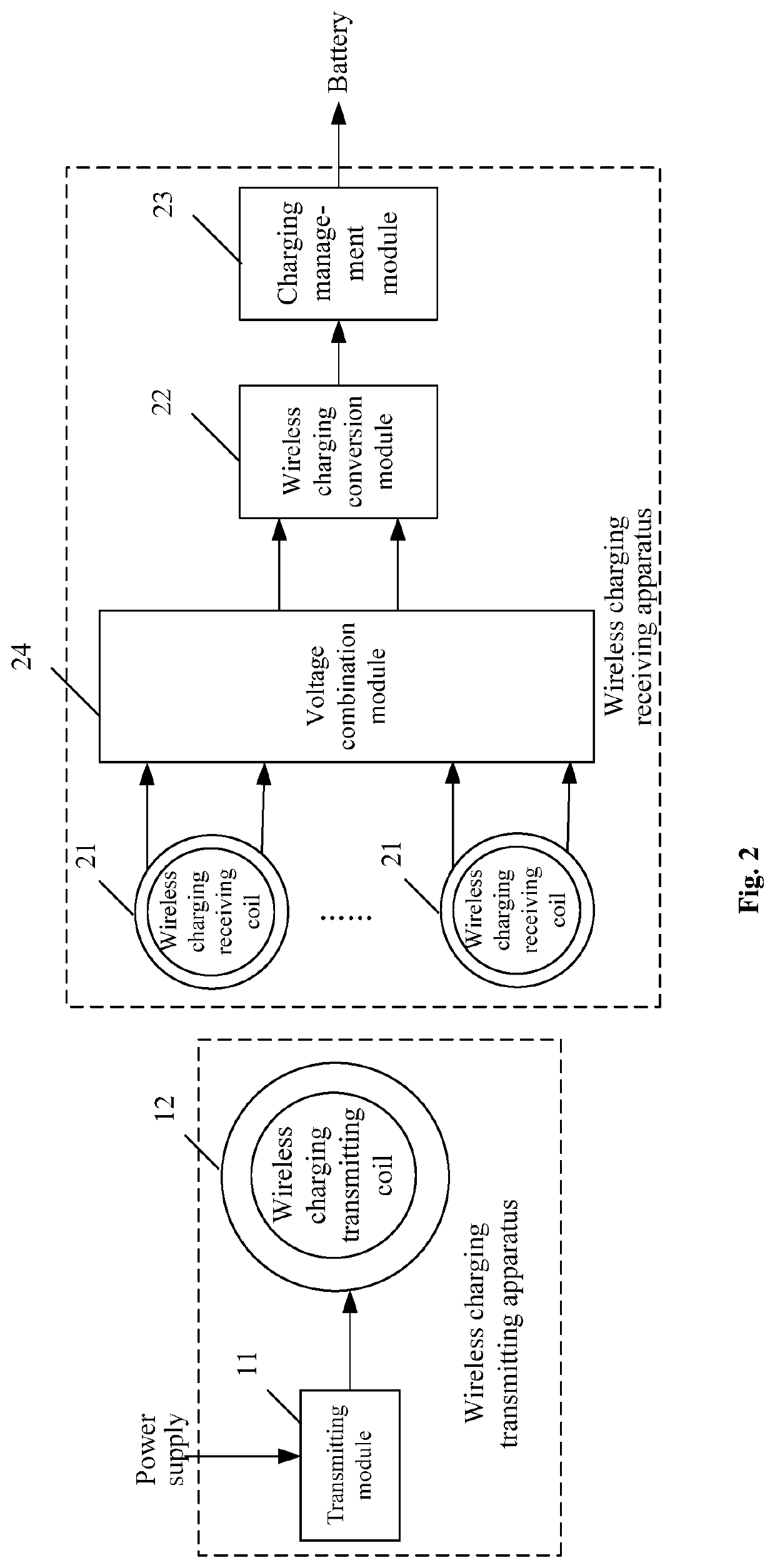
The wireless charging receiving apparatus described in this patent aims to address the issue of excessive heat generation during wireless charging. It includes a conversion module, a charging management module, and two wireless charging receiving coils. The wireless charging receiving coils are connected to the voltage combination module, which then sends alternating-current electromagnetic induction signals to the conversion module. This module then outputs superposed alternating-current electrical signals to the charging management module, which charges a battery using the received direct-current electrical signals. This technology results in less heat generation during wireless charging and provides a safer and more efficient charging experience.

Problems solved by technology

However, in actual use, the wireless charging is accompanied by serious heat generation.
When testing is performed to a wireless charging product less than 5 W, it is also found that heat generation is very serious as well when an output current is large.
Serious heat generation occurs when the mobile terminal is charged wirelessly.
On one hand, the mobile terminal is very hot after being removed from a charging panel, which affects the user experience; and on the other hand, long-time charging may cause battery bulging, which affects the battery life.
However, because the manganese-zinc ferrite has a small resistivity, an eddy current will still be generated in the ferrite, which causes heat generation in the ferrite.
This method cannot fundamentally avoid a circumstance of heat generation for the wireless charging fast charger.

Method used


Image

  • Wireless charging receiving apparatus, method for realizing wireless charging, and mobile terminal
  • Wireless charging receiving apparatus, method for realizing wireless charging, and mobile terminal
  • Wireless charging receiving apparatus, method for realizing wireless charging, and mobile terminal

Examples


Embodiment Construction

[0034]Embodiments of the present disclosure will be illustrated in detail hereinafter in combination with the accompanying drawings to make the purpose, technical solutions, and advantages of the present disclosure more clear. It should be noted that, as long as there is no conflict, the embodiments and the technical features mentioned in the embodiments may be combined with one another in any manner.

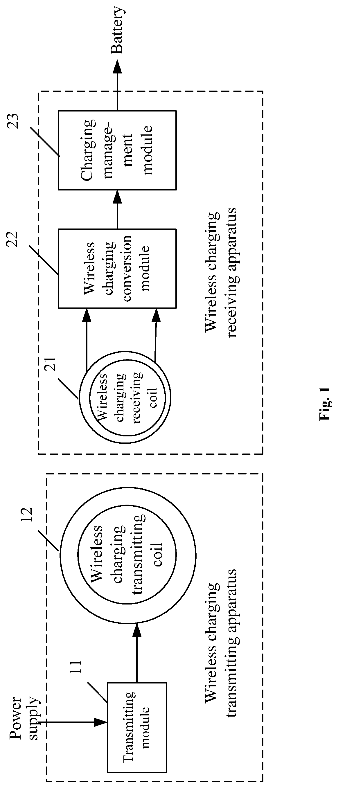
[0035]At present, a solution that a receiving terminal has a single coil is generally adopted for wireless charging, and the receiving terminal is located at a center of a battery. As shown in FIG. 1, a wireless charging transmitting apparatus includes a transmitting module 11 and a wireless charging transmitting coil 12. The transmitting module 11 receives power from a power supply, and outputs electric signals to the wireless charging transmitting coil 12. A wireless charging receiving apparatus includes a wireless charging receiving coil 21, wireless charging conversion module 22 and...


PUM


Abstract

A wireless charging receiving apparatus includes a wireless charging conversion module, a charging management module, a voltage combination module and at least two wireless charging receiving coils. The at least two wireless charging receiving coils are used to couple with a wireless charging transmitting coil in a wireless charging transmitting apparatus and output alternating-current electromagnetic induction signals to the voltage combination module; the voltage combination module is used to carry out voltage superposition on the alternating-current electromagnetic induction signals output by the at least two wireless charging receiving coils and output superposed alternating-current electrical signals to the wireless charging conversion module; the wireless charging conversion module is used to convert received alternating-current electrical signals into direct-current electrical signals, and output the direct-current electrical signals to the charging management module; and the charging management module is used to charge a battery by means of received direct-current electrical signals.

Description

CROSS-REFERENCE TO RELATED APPLICATIONS[0001]This application claims the priority of Chinese patent application CN 201810746388.8, entitled “Wireless Charging Receiving Apparatus, Method for Realizing Wireless Charging, and Mobile Terminal” and filed on Jul. 9, 2018, the entirety of which is incorporated herein by reference.FIELD OF THE INVENTION[0002]The present disclosure relates to the technical field of charging, and in particular, to a wireless charging receiving apparatus, a method for realizing wireless charging, and a mobile terminal.BACKGROUND OF THE INVENTION[0003]A mobile terminal wireless charging technology refers to charging a mobile terminal wirelessly, and may generally include an electromagnetic induction manner and a magnetic resonance manner. The electromagnetic induction manner is more common.[0004]For the wireless charging technology using the electromagnetic induction manner, medium power wireless charging with a receiving terminal having a power of greater tha...

Claims


Application Information

Patent Timeline
IPC IPC(8): H02J50/40H02J50/10H02J7/04
CPCH02J50/402H02J7/04H02J50/10
Inventor CHEN, BINGKUANCHEN, TAO
Owner ZTE CORP
Learn More