Orthopedic implant rod reduction tool set and method

a technology of orthopedic implants and tool sets, applied in the field of orthopedic implant rod reduction tool sets and methods, to achieve the effects of convenient attachment and disengagement, low cost, and convenient us

Active Publication Date: 2005-09-01
NUVASIVE
View PDF25 Cites 352 Cited by
  • Summary
  • Abstract
  • Description
  • Claims
  • Application Information

AI Technical Summary

Benefits of technology

[0007] Therefore, the objects of the present invention are: to provide a set of tools for implanting a spinal rod for support or alignment along a human spine with minimal surgical invasion of the patient; to provide such a set of tools including a pair of end tool guides for slidably guiding opposed ends of the rod toward end bone screws attached to the end guide tools; to provide such a set of tools including intermediate guide tools for each intermediate bone screw that guide the rod in slots therethrough to respective bone screws; to provide such a set of tools including rod pusher and closure top installation tools for assisting in securing the rod in the bone screws; to provide such a set of tools where the end guide tools include a longitudinal channel extending upwardly from near a bottom thereof to slidingly receive and guide ends of the rod toward associated end bone screws; to provide such a set of tools wherein the guide tools are easily attached to and disengaged from the bone screws; to provide such a set of tools wherein each guide tool includes a first guide and advancement structure near the bottom thereof that receives thread or locking flange mating structure on the closure top and advances the closure top upon rotation of the closure top to urge the rod downwardly; to provide such a set of tools wherein the guide tool first guide and advancement structure acts cooperatively with a second guide and advancement structure on the bone screw so as to transfer the closure top upon rotation thereof from the guide tool to the bone screw while continuously applying pressure to the rod and thereafter further advance the closure top to urge the rod into a seated position in

Problems solved by technology

This presents a problem with implantation of rods that are elongate and have historically required a long incision and open wound in order to prov

Method used


Image

  • Orthopedic implant rod reduction tool set and method
  • Orthopedic implant rod reduction tool set and method
  • Orthopedic implant rod reduction tool set and method

Examples


Embodiment Construction

[0034] As required, detailed embodiments of the present invention are disclosed herein; however, it is to be understood that the disclosed embodiments are merely exemplary of the invention, which may be embodied in various forms. Therefore, specific structural and functional details disclosed herein are not to be interpreted as limiting, but merely as a basis for the claims and as a representative basis for teaching one skilled in the art to variously employ the present invention in virtually any appropriately detailed structure.

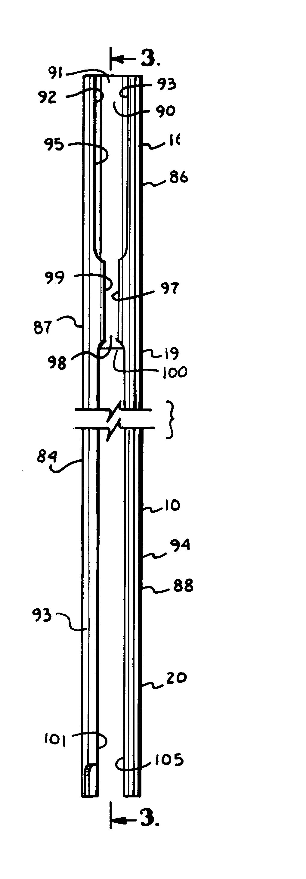
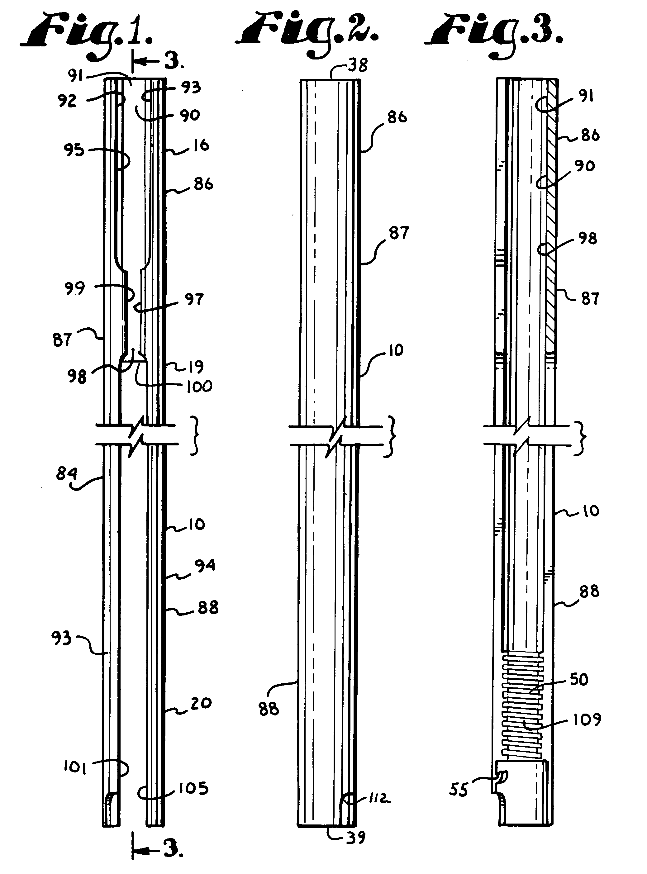
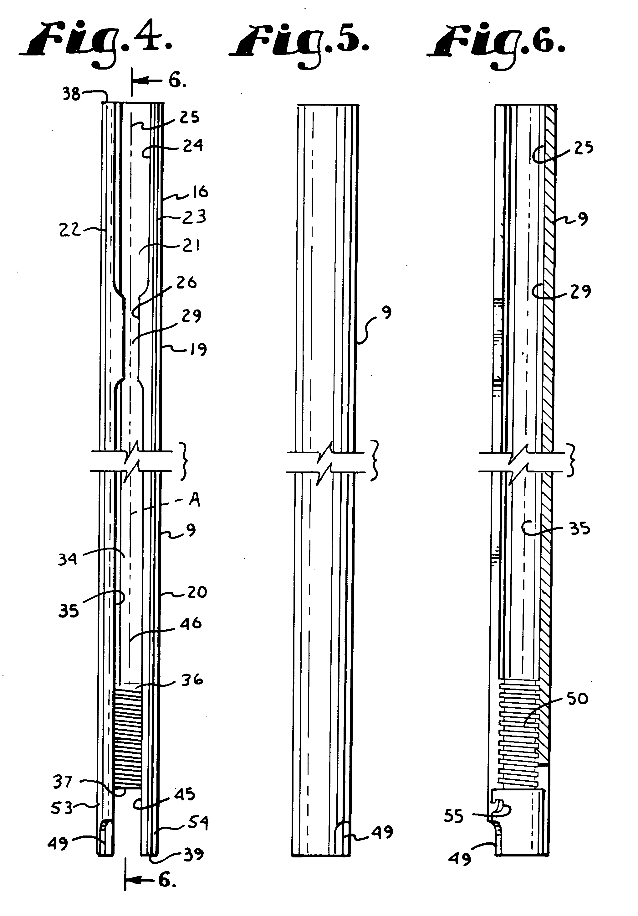
[0035] The reference numeral 1 generally designates a tool set for use in installing an orthopedic spinal rod 4 into a set of bone screws 6 in accordance with the present invention.

[0036] The tool set 1 of the illustrated embodiment includes a pair of end guide tools 9 and a plurality of intermediate guide tools 10, which in the illustrated embodiment includes a pair of intermediate guide tools 10 on each side of a patient's spine 17, but which can include...


PUM


Abstract

A tool set for implanting a rod in a human spine in conjunction with bone screws. The tool set includes a pair of end guide tools that receive opposite ends of the rod in channels and under manipulation by a surgeon facilitate transport of the rod toward the bone screws attached to the guide tools. Intermediate guide tools having guiding pass through slots are utilized to guide intermediate locations along the rod toward associated bone screws. An attachment structure operably connects the guide tools to the bone screws. The guide tools each include a lower guide and advancement structure to allow a closure top with mating structure to be rotated and driven downward against the rod and to cooperate with similar structure in the bone screw to seat and lock the rod therein. A method utilizing the tool set allows a surgeon to percutaneously implant the rod in the patient.

Description

BACKGROUND OF THE INVENTION [0001] The present invention relates to apparatuses and methods for use in performing spinal surgery and, in particular, to tools and methods of using such tools, especially for percutaneously implanting a rod for spinal support and alignment using minimally invasive techniques. [0002] For many years, spinal osteosynthesis apparatuses have been utilized to correct spinal deformities, injuries or disease. In such procedures, elongate rods are surgically attached to vertebrae of the spine to provide support and / or to reposition certain vertebrae. Such rods are secured to vertebrae utilizing bone screws and other implants. [0003] Surgical techniques and bone screws have improved; however, in order to reduce the impact of such surgery on the patient, it has been desirable for such implants to be inserted percutaneously or with surgical techniques that are minimally invasive to the body of the patient. This presents a problem with implantation of rods that are...

Claims


Application Information

Patent Timeline
IPC IPC(8): A61B17/70A61B17/88
CPCA61B17/7011A61B17/7032A61B17/7037A61B17/7085A61B17/7035A61B17/7088A61B2017/564A61B17/7001A61B17/7002A61B17/7091A61B17/7076A61B17/7089A61B17/7082A61B17/7086A61B2090/037A61B17/7008A61B17/701A61B17/702A61B17/7038
Inventor JACKSON
Owner NUVASIVE
Why Eureka
Try Eureka