Gyroscopic navigation system and method

a navigation system and gyroscopic technology, applied in the field of aircraft instruments, can solve the problems of pilot disorientation, fatal crashes, and the cost of having a second set of primary instruments is prohibitively expensive for a small aircraft, and achieve the effects of reducing costs, simple retrofitting, and sensitive to extra weigh

Inactive Publication Date: 2005-09-01
SCHILLER PETER J +2
View PDF28 Cites 10 Cited by
  • Summary
  • Abstract
  • Description
  • Claims
  • Application Information

AI Technical Summary

Benefits of technology

[0023] Another advantage of the present invention is that the system is a plug and play, maintenance free unit. The absence of moving parts lends the solid-state gyros an exceptionally long life and, unlike traditional gyros, the gyros of the present invention generally will not need rebuilding, thereby significantly reducing the cost.
[0024] A further advantage of the present invention is that the system is lightweight. Many pilots, especially those with a smaller high-performance aircraft, are particularly sensitive to extra weight. The weight of the system is preferably approximately 2.0 pounds or less, more preferably 1.0 pound or less.
[0025] An additional advantage of the present invention is that the system is rugged and is designed to withstand shocks of 1000 Gs or more.
[0026] Yet another advantage of the present invention is that the system is simple to retrofit. The system is compact and capable of fitting a standard instrument panel opening in the cockpit of an aircraft.
[0027] With respect to the heart of the standby navigation system, i.e. the gyros, the system in accordance with the principles of the present invention includes a solid-state micro-gyroscope (or “gyro”). The gyro generates a voltage output proportional to rotational rate. The gyro utilizes a plurality of precision thin-film piezoelectric elements to detect rotation, such as pitch, roll, and yaw, while rejecting spurious noise created by vibration, thermal gradients, and electromagnetic interference. During a normal operation, selected piezoelectric elements on the gyro are driven by a periodic signal to create a controlled mechanical oscillation. When the gyro is subjected to rotational motion, such as pitch, roll, or yaw, a characteristic voltage is produced across other piezoelectric elements on the gyro, according to the Coriolis Effect. These voltages are amplified and filtered to extract high-fidelity signals proportional to the rate of rotation.
[0028] Generally, piezoelectric materials are used in a variety of sensors and actuators. Piezoelectric materials convert mechanical energy to electrical energy and vice versa. For instance, if pressure is applied to a piezoelectric crystal, a voltage is generated in proportion thereby producing the function of a sensor. Generation of an electrical signal in response to an applied force or pressure is known as the “primary piezoelectric effect”. Similarly, if an electrical voltage is applied to a piezoelectric crystal, it expands in proportion as an actuator. Geometric deformation (expansion or contraction) in response to an applied electric field is known as the “secondary piezoelectric effect”. Whether operated as a sensor or actuator, electrically-conductive electrodes must be appropriately placed on a crystal for collection or application of the electrical energy, respectively. Therefore, a piezoelectric sensor / actuator generally includes a) a portion of piezoelectric material, and b) electrically-conductive electrodes suitably arranged to direct / supply electrical energy to / from an electrical circuit, e.g. an amplifier / an external power source.

Problems solved by technology

Loss of vacuum or electrical power, especially during instrument flight, renders these instruments useless and can result in pilot disorientation and, at times, fatal crashes.
However, the cost of having a second set of primary instruments is prohibitively expensive for a small aircraft.
In addition, a small aircraft is extremely sensitive to extra weight.
Further, cockpit size and instrument panel space are very limited in small aircraft.
However, the system is not user-friendly.
This increases pilot's cockpit management load, thereby reducing overall pilot awareness, which is considered dangerous in operating a small aircraft.
In addition, the Goodrich system is generally too heavy and too costly for a small aircraft.
Random noise are typically caused by characteristics of a device, such as the sensitivity of a sensor, etc.
However, due to the instability, gyro instruments can only hold for a certain period of time and then tend to drift back to a level position.

Method used


Image

  • Gyroscopic navigation system and method
  • Gyroscopic navigation system and method
  • Gyroscopic navigation system and method

Examples


Embodiment Construction

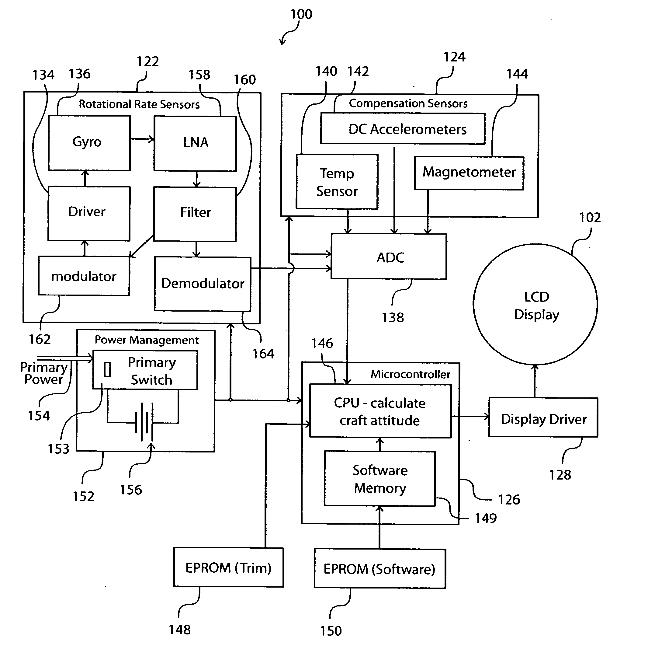
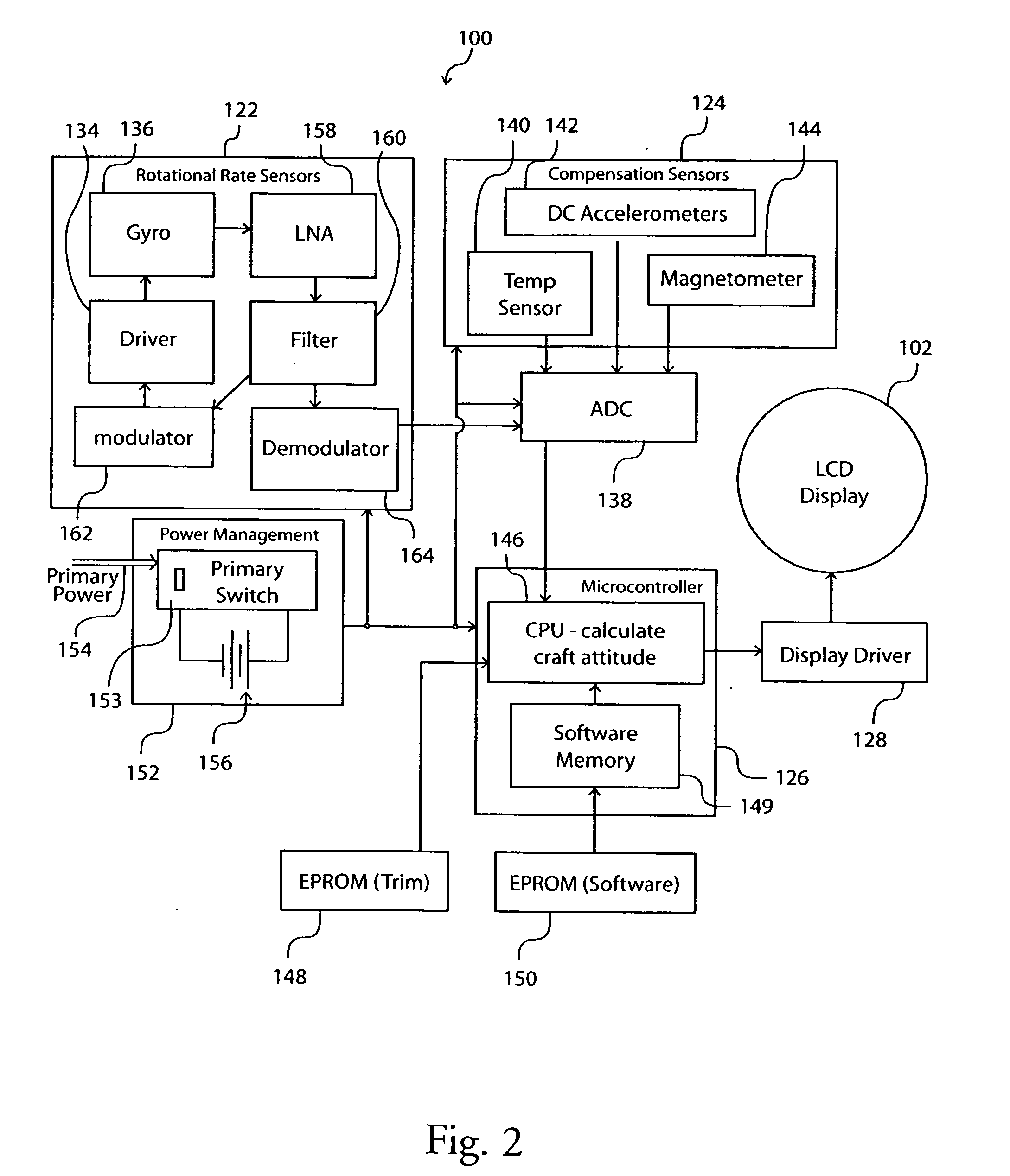
[0052] As an example, a standby gyroscopic navigation system 100 is disclosed in preferred embodiments of the present invention. It is appreciated that the system in accordance with the present invention may be used as a primary navigation system. The preferred embodiments of the present invention provide a three-dimensional, solid-state gyroscopic navigation system that is battery-driven and functions independently of the aircraft's primary power systems, both electric and vacuum.

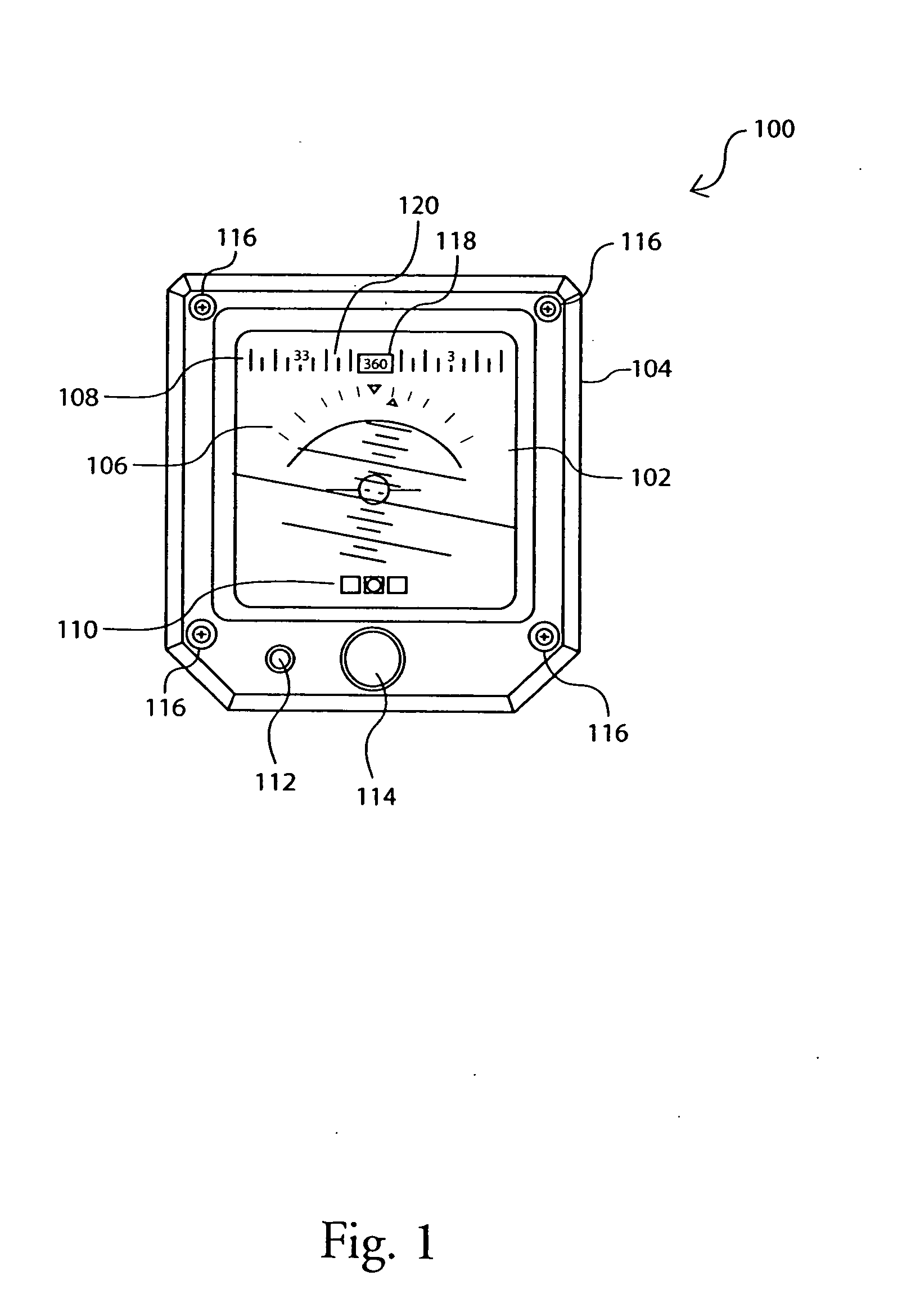
[0053] Preferred embodiments of the standby gyroscopic navigation system 100 as shown in FIGS. 1-10 include high-performance solid-state gyroscopes, on-board signal processing electronics, color liquid crystal display (LCD), a back-up battery, and other sensors, such as magnetometers, etc.

[0054] The present invention reflects the trend to reduce pilot workload by displaying multiple functions on a single display. The system 100 simultaneously displays data, traditionally provided by three separate instru...


PUM


Abstract

A compact, lightweight, cost effective, self-contained standby electronic navigation system with high signal-to-noise ratio and good dynamic stability is provided. The system includes a first sensor module for providing a plurality of rotational rate signals, a second sensor module for providing a plurality of compensation signals, and a microcontroller module for processing the rotational rate signals and the compensation signals and sending the signals to a display for displaying attitude information, directional information, and turn coordinate information on a single screen simultaneously. In one embodiment, the first sensor module includes a plurality of rotational sensors made of piezoelectric elements. The piezoelectric elements are made from a single sheet of piezoelectric material so that the elements possess uniform characteristics, and are arranged to reduce systematic drift and random noise normally present in a rotational rate sensor. The sensors can be configured on a single multi-sensor chip.

Description

CROSS-REFERENCE TO RELATED APPLICATION(S) [0001] This application claims benefit under 35 U.S.C. § 119(e) to U.S. application Ser. No. 10 / 055,186, filed Jan. 23, 2002, entitled “Gyroscopic Navigation System and Method” (Attorney Docket No. 14143), the contents of which are incorporated herein in their entirety for all purposes.FIELD OF THE INVENTION [0002] The present invention relates generally to aircraft instruments, and more particularly, to a gyroscopic navigation system for a small aircraft's primary instruments, such as an attitude indicator (AI), a directional gyro (DG), and a turn coordinator (TC) / slip-skid indicator. BACKGROUND OF THE INVENTION [0003] All aircraft, large and small, production or experimental, depend on gyroscopes for a variety of navigational data. Most aircraft utilize mechanical or spinning-mass gyros to derive information, such as heading and attitude. Often housed in a remote location, an aircraft's gyro (or gyros) feed data back to a cockpit, which ar...

Claims


Application Information

Patent Timeline
Patent Type & Authority Applications(United States)
IPC IPC(8): G01C19/5719G01C23/00H01L41/08
CPCG01C23/00G01C19/5719
Inventor SCHILLER, PETER J.MONCUR, TIMOTHY R.JOHNSON, BARRON
Owner SCHILLER PETER J
Why Eureka
Try Eureka