
Wind power generating system

a wind power generating system and wind power technology, applied in the direction of electric generator control, machines/engines, mechanical equipment, etc., can solve the problems of inability to produce a useful amount of electric energy, power output fluctuation a great deal, and more wide spread use of wind power energy, so as to achieve a relatively large amount of electric energy

Inactive Publication Date: 2005-09-08
MAG POWER JAPAN
View PDF10 Cites 13 Cited by
  • Summary
  • Abstract
  • Description
  • Claims
  • Application Information

AI Technical Summary

Benefits of technology

[0003] In view of such problems of the prior art, a primary object of the present invention is to provide a wind power generating system that can produce a relatively large amount of electric energy even when the wind speed is low.
[0004] A second object of the present invention is to provide a wind power generating system that can operate over a relatively wide range of wind speed, and can be manufactured at low cost.
[0009] In view of minimizing the manufacturing cost, the turbine blades of the first and second turbines may be each provided with a fixed pitch angle.

Problems solved by technology

Various advantages of the wind power generating system are widely known but it is also known that there are some disadvantages that prevent more wide spread use of wind power energy.
One of the disadvantages is that the power output fluctuates a great deal because the wind speed is not constant and largely unpredictable.
In spite of extensive research efforts, conventional wind power generating systems are not able to produce a useful amount of electric energy when the wind speed drops below a certain level.
In most cases, a useful amount of electricity may not be produced during a large part of each day.

Method used


Image

  • Wind power generating system
  • Wind power generating system
  • Wind power generating system

Examples


Embodiment Construction

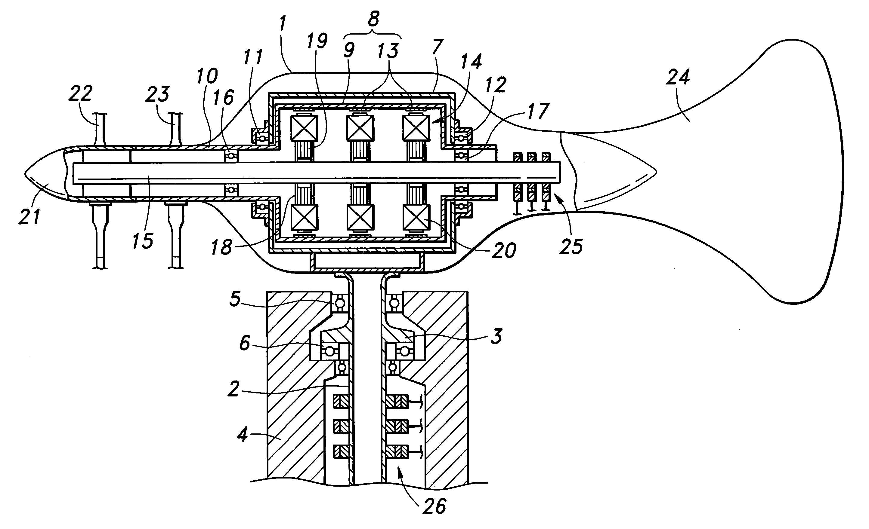
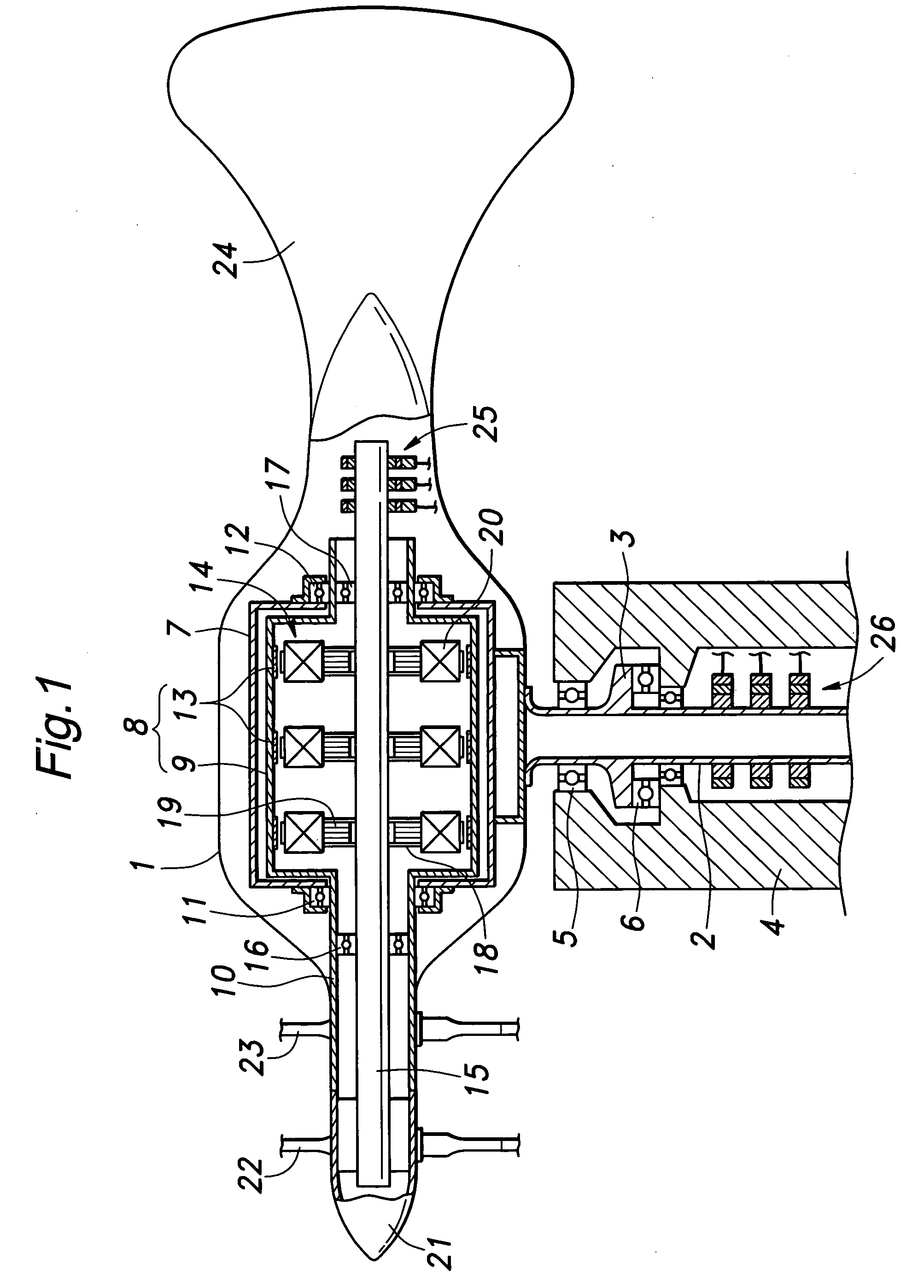
[0017]FIG. 1 shows a wind power generating system (or windmill electric generator system) embodying the present invention. An aerodynamically shaped housing 1 is provided with a support shaft 2 that depends vertically downward from the housing along a line passing through the gravitational center of the system. The support shaft 2, is provided with a radial flange 3. The support shaft 2 is rotatably supported by a fixed base 4 via a radial bearing 5 and a thrust bearing 6.

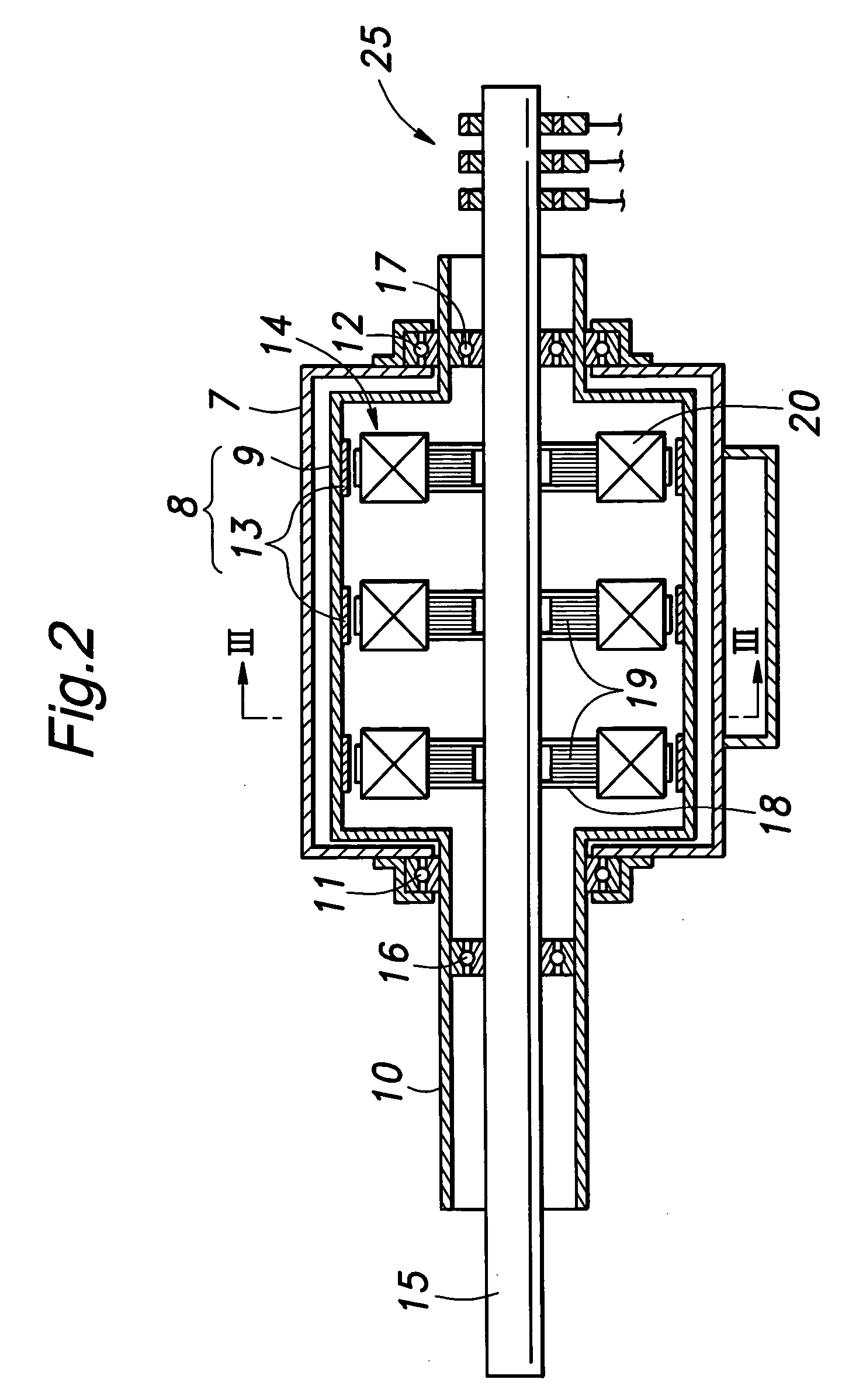
[0018] A generally cylindrical inner housing 7 is fixedly secured in the generator housing 1. A generally cylindrical outer rotor 8 is rotatably supported by the inner housing 7 via a front bearing 11 and a rear bearing 12. The outer rotor 8 is provided with a hollow cylindrical member 9, and a front extension 10 which is disposed coaxially with the cylindrical member 9 and reduced in diameter from the cylindrical member 9. A plurality of permanent magnets 13 are attached to the inner circumferential surface of th...


PUM


Abstract

In a wind power generating system, a pair of axially spaced turbines are connected to an outer rotor and an inner rotor of a generator, respectively, and are provided with blades having equal but opposite pitch angles so that the inner and outer rotor rotate at a same rotational speed in opposite directions. Because the relative rotational speed between the inner and outer rotors is twice as great as the rotational speed of the inner rotor or outer rotor, the generator system can produce a relatively large electric power even when the wind speed is low. If desired, a pitch varying mechanism for the turbine blades may be done away with so as to reduce the manufacturing and maintenance costs.

Description

TECHNICAL FIELD [0001] The present invention relates to a wind power generating system, and in particular to a wind power generating system that can produce a relatively large amount of electricity even when the wind speed is low. BACKGROUND OF THE INVENTION [0002] Various advantages of the wind power generating system are widely known but it is also known that there are some disadvantages that prevent more wide spread use of wind power energy. One of the disadvantages is that the power output fluctuates a great deal because the wind speed is not constant and largely unpredictable. There are areas where wind blows more or less constantly. However, a larger majority of areas experience wind of highly fluctuating wind speeds. In spite of extensive research efforts, conventional wind power generating systems are not able to produce a useful amount of electric energy when the wind speed drops below a certain level. In most cases, a useful amount of electricity may not be produced during...

Claims


Application Information

Patent Timeline
IPC IPC(8): F03D9/00H02P9/04
CPCY02E10/725H02K7/183Y02E10/72
Inventor KURACHI, HARUKICHIARITAKA, SATORUKONSE, MOTOHARU
Owner MAG POWER JAPAN
Learn More