Electro-optical device, driving method of electro-optical device, driving circuit of electro-optical device and electronic apparatus

a driving circuit and electro-optical technology, applied in the direction of electric digital data processing, instruments, computing, etc., can solve problems such as display image deterioration

Active Publication Date: 2005-09-08
SEIKO EPSON CORP
View PDF4 Cites 21 Cited by
  • Summary
  • Abstract
  • Description
  • Claims
  • Application Information

AI Technical Summary

Benefits of technology

[0015] An aspect of the invention can provide an electro-optical device capable of securing uniformity of display quality in a screen, suppressing occurrence of disclination, and preventing problems such as insufficient writing from occurring, a driving method of the electro-optical device, a driving circuit of the electro-optical device, and an electronic apparatus employing the electro-optical device.
[0019] According to this structure, the scanning drive circuit generates the scanning signals on the basis of the outputs of the transmission clock generator and the scanning start pulse generator. Accordingly, the scanning operation in the display unit is synchronized with the independent transmission clock, so that it is possible to obtain a sufficient writing time before and after the start timing of the vertical period and to continuously and constantly write the writing image.
[0022] The scanning drive circuit selects n scanning lines (n is an integer greater than or equal to 2) spaced from each other to sequentially supply gate pulses to the selected scanning lines in one horizontal period of an input image corresponding to the number of pixels in the display unit, and shifts the selected n scanning lines by one line in a next horizontal period. Accordingly, the most adjacent lines are driven with the image signals having the same polarity, so that it is possible to prevent a transverse electric field at the time of the surface inversion driving. As a result, it is possible to secure a uniform display quality in a screen and to prevent or reduce the occurrence of disclination. Since the timing of performing the vertical scanning operation is controlled by the independent transmission clock, the cycle of the transmission clock is not varied before and after the start timing of the vertical period, so that it is possible to continuously and constantly write the writing image for a sufficient writing time, even when the number of horizontal periods in one vertical period is not an integer or when the number of horizontal scanning lines in one vertical period is odd.
[0024] According to this structure, the transmission clock is generated in synchronism with the signal having a frequency equal to the horizontal frequency of the input image signals. The vertical reset signal is generated in synchronism with the transmission clock, and the scanning start pulse for controlling the start timing of the vertical scanning operation is generated on the basis of the transmission clock and the vertical reset signal. That is, the timing signals for the vertical scanning operation are synchronized with the independent transmission clock. As a result, the cycle of the transmission clock is not varied before and after the start timing of the vertical period, so that it is possible to continuously and constantly write the writing image for a sufficient writing time, even when the number of horizontal periods in one vertical period is not an integer or when the number of horizontal scanning lines in one vertical period is odd.
[0025] The transmission clock may be generated on the basis of a dot clock. According to this structure, it is possible to generate the independent transmission clock synchronized with the signal having a frequency equal to the horizontal frequency of the input image signals with high accuracy.
[0028] According to another aspect of the invention, there is also provided an electronic apparatus including the electro-optical device described above. According to this structure, it is possible to obtain high-quality images without bad influences of the transverse electric field and the crosstalk.

Problems solved by technology

However, in this driving method, when the number of horizontal scanning lines in one horizontal period is odd or not an integer, the writing time is insufficient at the time of changing the vertical period, thereby deteriorating a display image.

Method used


Image

  • Electro-optical device, driving method of electro-optical device, driving circuit of electro-optical device and electronic apparatus
  • Electro-optical device, driving method of electro-optical device, driving circuit of electro-optical device and electronic apparatus
  • Electro-optical device, driving method of electro-optical device, driving circuit of electro-optical device and electronic apparatus

Examples


Embodiment Construction

[0047] Now, exemplary embodiments of the invention will be described in detail with reference to the drawings. FIGS. 1 to 16 illustrate an exemplary embodiment of the invention. In the drawings, in order to recognize respective layers or respective members from the drawings, the respective layers or the respective members have different scales.

[0048] In the exemplary embodiment, an example where the invention is applied to a liquid crystal light valve used as a light modulating device of a projection display apparatus is described.

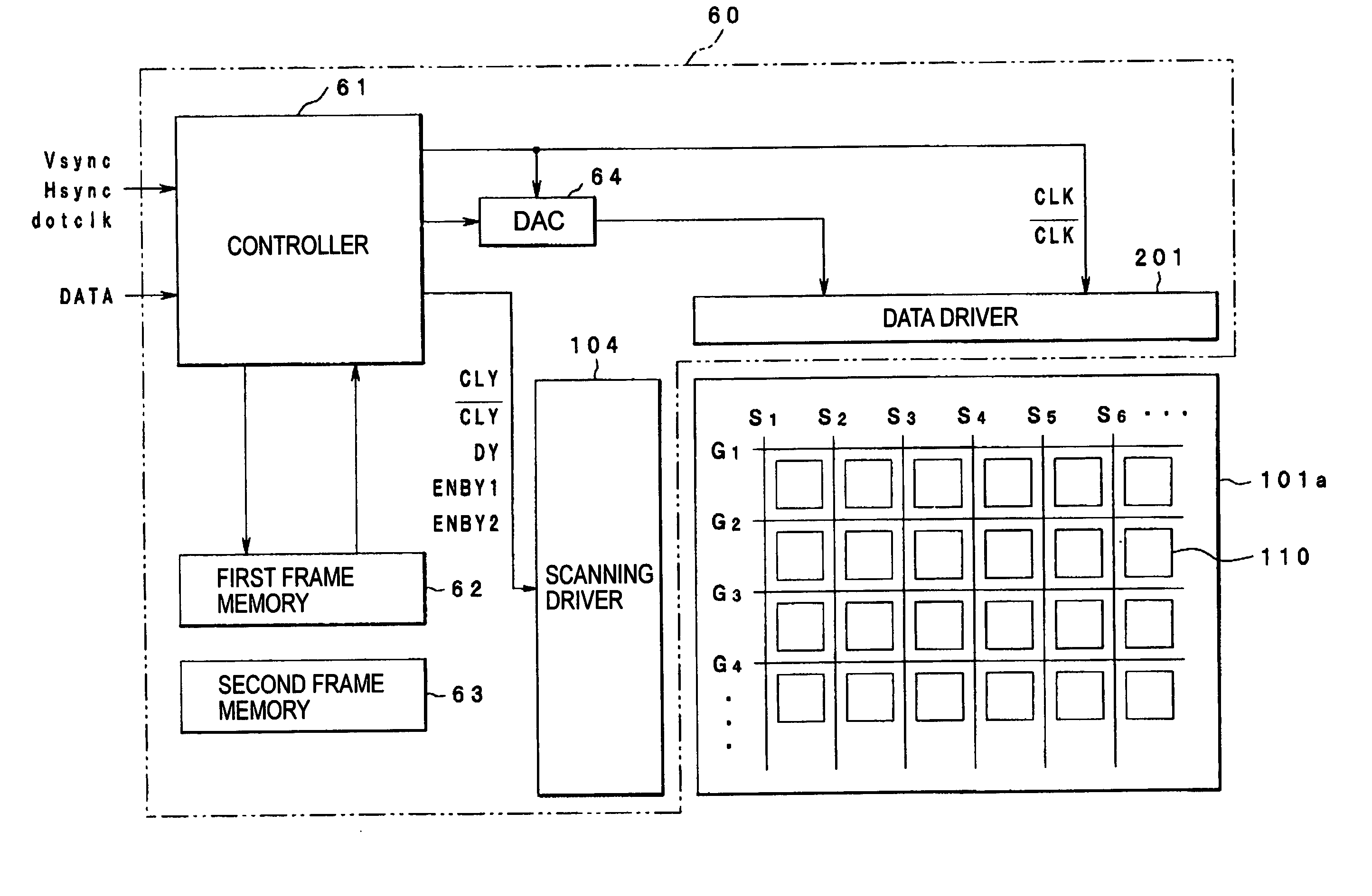
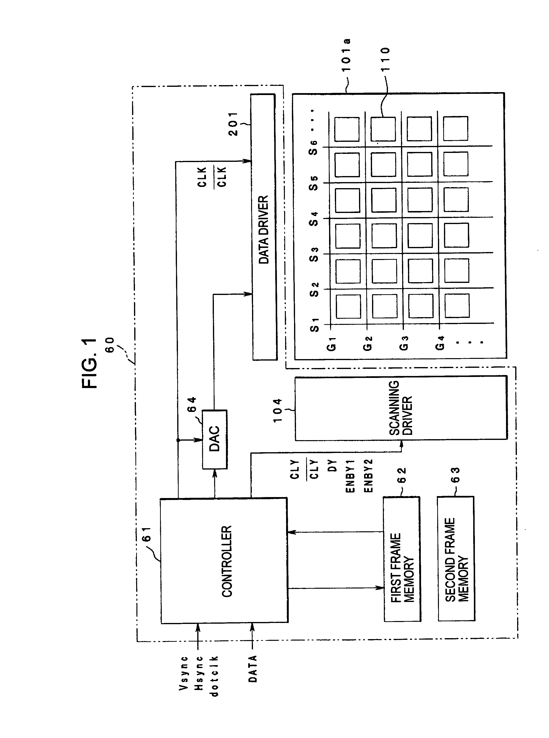
[0049] The electro-optical device according to the embodiment can include a display area 101a employing a liquid crystal as an electro-optical material, a scanning driver 104 and a data driver 201 for driving the pixels in the display area 101a, a controller 61 for supplying various signals to the scanning driver 104 and the data driver 201, a DC converter (DAC) 64, and first and second frame memory 62 and 63.

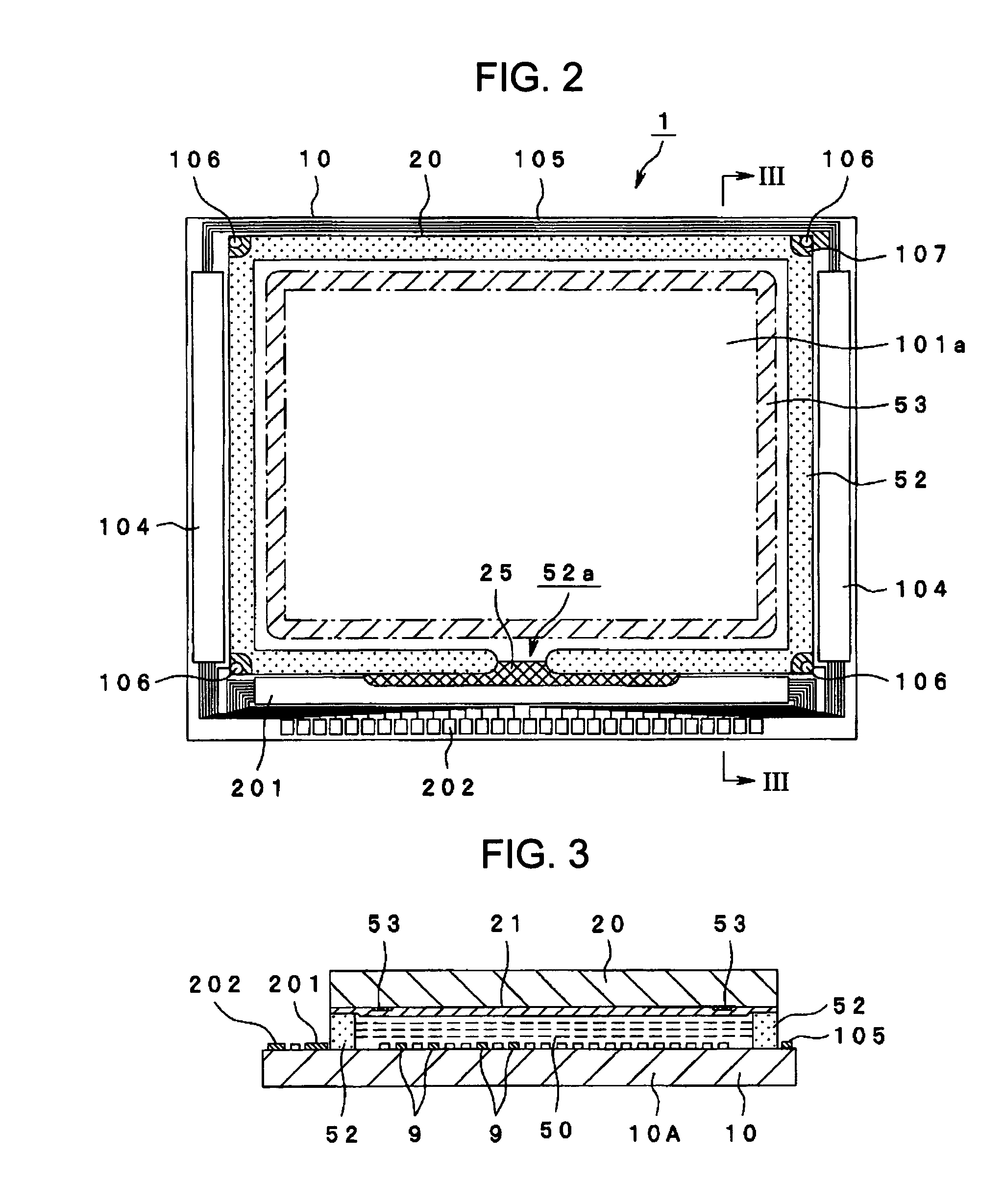
[0050]FIG. 2 show a schematic structure of a...


PUM

PropertyMeasurementUnit
frequencyaaaaaaaaaa
horizontal frequencyaaaaaaaaaa
polarityaaaaaaaaaa

Abstract

Aspects of the invention can provide a driving circuit of an electro-optical device that can reduce or prevent bad influences of a transverse electric field and a crosstalk. There can be provided a driving circuit of an electro-optical device, the driving circuit generating timing signals for supplying scanning signals to a display unit in which pixels can be formed corresponding to the respective intersections between a plurality of data lines and a plurality of scanning lines arranged in a matrix shape and the switching elements provided in the pixels are turned on by the scanning signals supplied to the scanning lines, so that the image signal supplied to the data lines are applied to the pixel electrodes of the pixels through the switching elements to drive the display unit. The driving circuit can include a transmission clock generating device for generating a transmission clock for sequentially transmitting the scanning signals to the scanning lines in synchronism with a signal having a frequency equal to a horizontal frequency of input image signals and outputting the transmission clock as a timing signal, a vertical reset signal generating device for generating a vertical reset signal synchronized with the transmission clock generated in close proximity of a vertical synchronizing signal of the input image signals, a scanning start pulse generating device for generating a scanning start pulse defining a start timing of a vertical scanning operation on the basis of the transmission clock and the vertical reset signal and outputting the scanning start pulse as a timing signal, and a writing image generating device for generating writing image signals to be supplied to the data lines by delaying the input image signals on the basis of the transmission clock and the vertical reset signal.

Description

BACKGROUND OF THE INVENTION [0001] 1. Field of the Invention [0002] Aspects of the invention can relate to an electro-optical device with a reduced cross-talk, a driving method of the electro-optical device, a driving circuit of the electro-optical device, and an electronic apparatus. [0003] 2. Description of Related Art [0004] Related art liquid crystal display devices using a liquid crystal as an electro-optical material, which are an example of electro-optical devices, have been widely used, as display devices taking the place of cathode ray tubes (CRT), for display units of various data processing instruments, liquid crystal televisions, and the like. [0005] Such related art liquid crystal display devices can include an element substrate provided with pixel electrodes arranged in a matrix shape and switching elements, such as TFT (Thin Film Transistors) connected to the pixel electrode, a counter substrate on which a counter electrode opposing the pixel electrodes is formed, and...

Claims


Application Information

Patent Timeline
Patent Type & Authority Applications(United States)
IPC IPC(8): G02F1/133G09G3/20G09G3/36
CPCG09G3/3614G09G3/3677G09G2320/0209G09G2310/0286G09G2310/061G09G2300/08G02F1/133
Inventor IISAKA, HIDEHITO
Owner SEIKO EPSON CORP
Why Eureka
Try Eureka