
Polarized interference recycling backlight module and liquid crystal display incorporating the same

a backlight module and polarized interference technology, applied in the direction of instruments, polarising elements, optical light guides, etc., can solve the problems of degradation of the performance of the backlight module, the lcd device does not emit light by itself, and the transmission of incident light is relatively high

Inactive Publication Date: 2005-09-08
NITTO DENKO CORP
View PDF27 Cites 26 Cited by
  • Summary
  • Abstract
  • Description
  • Claims
  • Application Information

AI Technical Summary

Benefits of technology

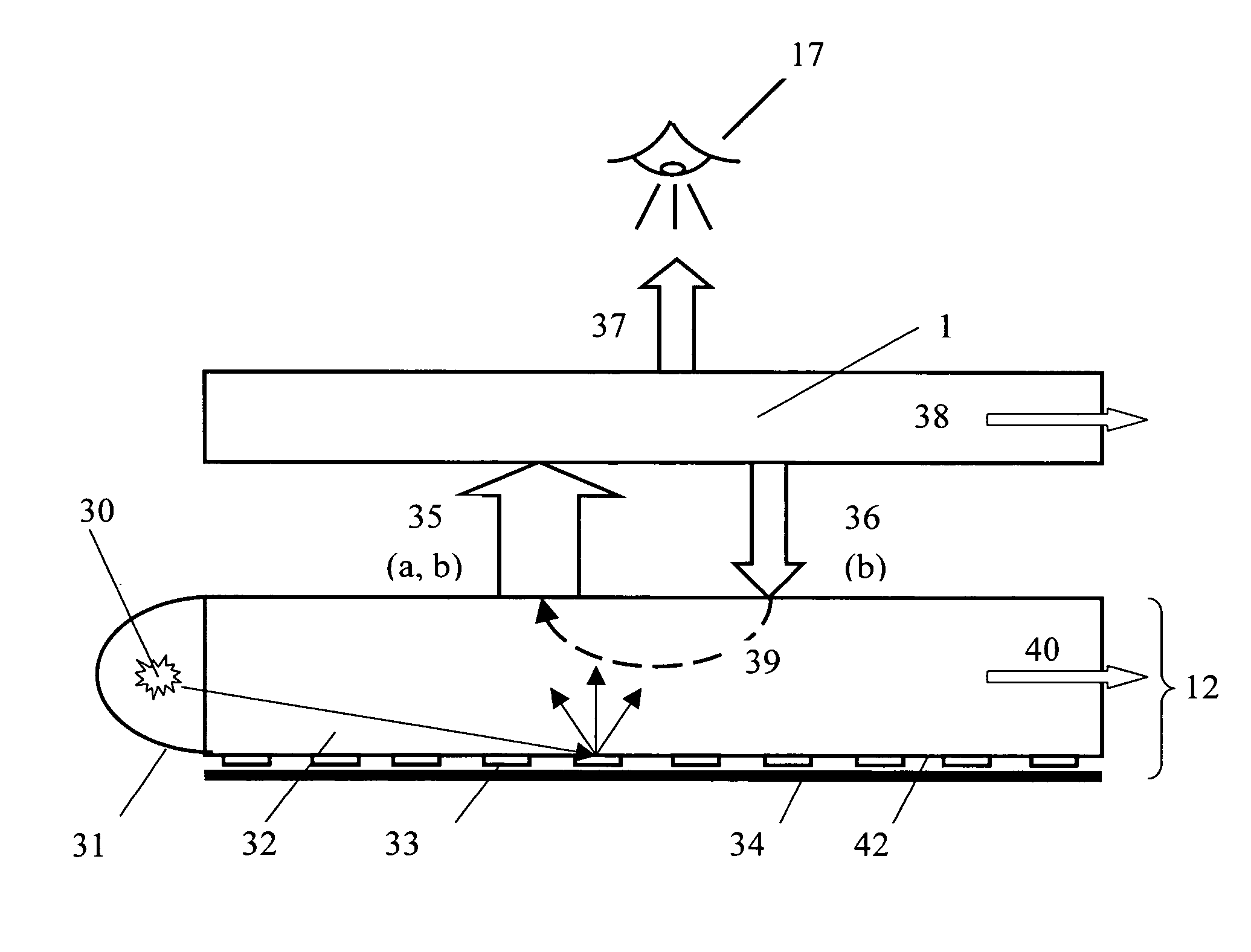
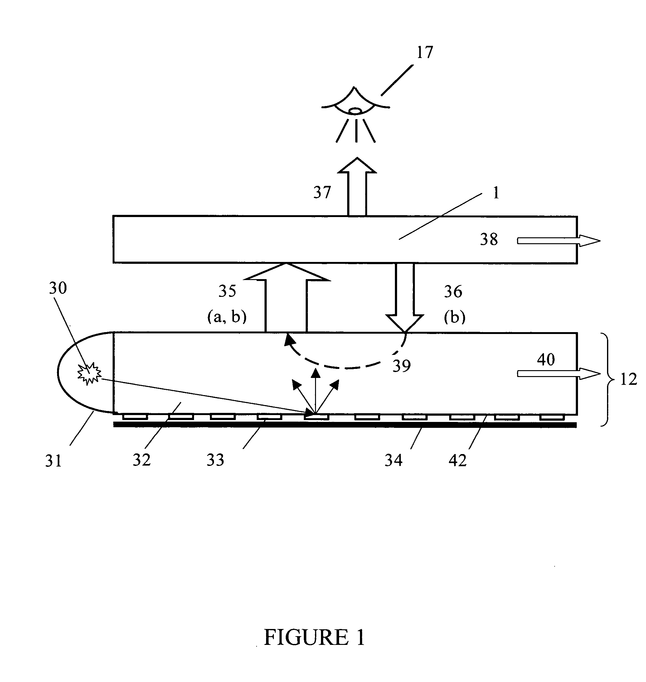
[0011] The disclosed invention represents a polarized interference recycling backlight module. The backlight module comprises an optical cavity serving as a light source, which is capable of reflecting and randomizing light incident upon a front surface of said optical cavity, and an I-Polar comprised of stacked layers, which is situated on the front surface of the optical cavity, which ensures transmission of light of predetermined polarization state and reflection of light with orthogonal polarization state in at least one region of the spectrum of light.

Problems solved by technology

LCD devices, however, do not emit light by themselves, and only control the transmission of incident light.
The main disadvantage of conventional reflectors used in the lamp cavity and at the back surface of the light guide is the relatively high optical absorption and high transmission of incident light.
This fraction of light is obviously not available to the viewer; thereby the absorption and / or transmission lead to degradation of the backlight module performance.

Method used


Image

  • Polarized interference recycling backlight module and liquid crystal display incorporating the same
  • Polarized interference recycling backlight module and liquid crystal display incorporating the same
  • Polarized interference recycling backlight module and liquid crystal display incorporating the same

Examples


example 1

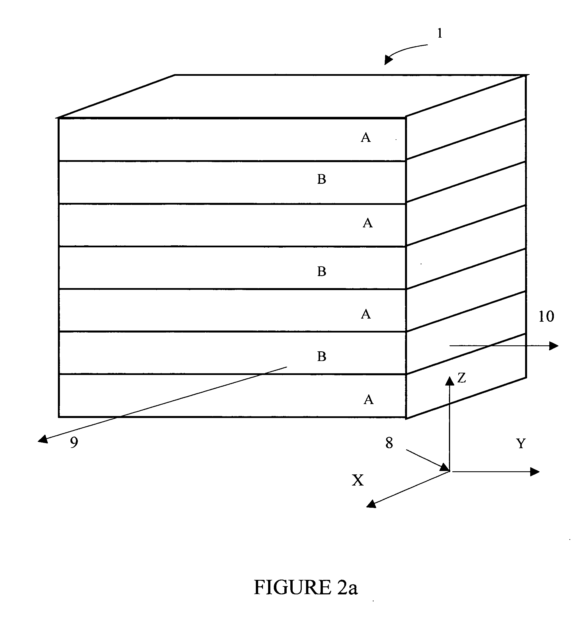
[0097] The typical interference polar (I-Polar) can be constructed using alternating layers of birefringent and isotropic materials deposited onto transparent substrate. Said interference polar has a transmission axis AB. If the unpolarized light is incident onto the interference polar, one part of this light, having the polarization approximately orthogonal to said transmission axis AB, is reflected from the interference polar. Desired performance can be achieved by manipulating the refractive index and thickness of each individual layer and the total number of layers. One of the most important aspects of the polarizer design is selection of the base structure. In the following consideration, normal incidence is assumed and the substrate index of refraction is fixed at 1.5. Typically, the interference polar can be designed in the form of a periodic structure of double layers with high and low refractive indices in the plane of polarization of the incident light. That is, the same p...


PUM


Abstract

A polarized interference recycling backlight module for generating light with a single polarization state, which reduces the optical loss in light beam output, is suitable for mass production, and decreases manufacturing costs, is disclosed. The backlight is easily integrated with conventional electro-optical display devices and achieves high-quality polarization. The polarized interference recycling backlight module according to the present invention comprises an optical cavity and interference polar (I-Polar) composed of stacked layers. At least one layer of said I-Polar is optically anisotropic and is made by means of Cascade Crystallization Process, is characterized by a globally ordered biaxial crystalline structure with an intermolecular spacing of 3.4±0.3 Å in the direction of one of optical axes, is transparent in the visible spectral range, and is formed by rodlike supramolecules representing at least one polycyclic organic compound with a conjugated π-system and ionogenic groups. Another aspect of the present invention is a liquid crystal display incorporating the polarized interference recycling backlight module.

Description

CROSS REFERENCE TO RELATED APPLICATIONS [0001] This application claims the priority of the united states provisional patent application Ser. No. 60 / 550,644, filed Mar. 4, 2004, the disclosure of which is hereby incorporated by reference in its entirety.FIELD OF THE INVENTION [0002] This invention relates generally to backlight modules for electro-optical display devices, and more particularly, to a backlight module for generating light with a single polarization state. BACKGROUND OF THE INVENTION [0003] Flat panel displays characterized by small thickness, low weight, and low power consumption find increasing use as displays in portable devices. Among flat panel displays of various types, liquid crystal display (LCD) devices are most widely used in laptop computers and desktop monitors because of their superior resolution, color image, and display quality. [0004] LCD devices use the optical anisotropy and polarization properties of liquid crystal molecules to produce a predetermined...

Claims


Application Information

Patent Timeline
IPC IPC(8): F21V8/00G02B6/00G02F1/1335
CPCG02B6/0036G02B6/0038G02B6/0043G02F1/13362G02B6/005G02B6/0056G02B6/0065G02B6/0046G02B5/30G02F1/1335
Inventor LAZAREV, PAVEL I.
Owner NITTO DENKO CORP
Learn More