Compensation of magnetic fields

Active Publication Date: 2005-09-08
IMS NANOFABTION
View PDF15 Cites 12 Cited by
  • Summary
  • Abstract
  • Description
  • Claims
  • Application Information

AI Technical Summary

Benefits of technology

[0007] The present invention sets out to overcome the above-mentioned shortcomings of the state of the art. While it is in general not too difficult to rule out interfering fields from the vicinity of the apparatus, it is often impossi

Problems solved by technology

While it is in general not too difficult to rule out interfering fields from the vicinity of the apparatus, it is often impossible for the operator of the apparatus to avoid intrusi

Method used


Image

  • Compensation of magnetic fields
  • Compensation of magnetic fields
  • Compensation of magnetic fields

Examples


Embodiment Construction

[0032] The preferred embodiment of the invention discussed in the following refers to a field compensation for a particle-optical system. It should be noted, however, that the invention is not restricted to this specific application.

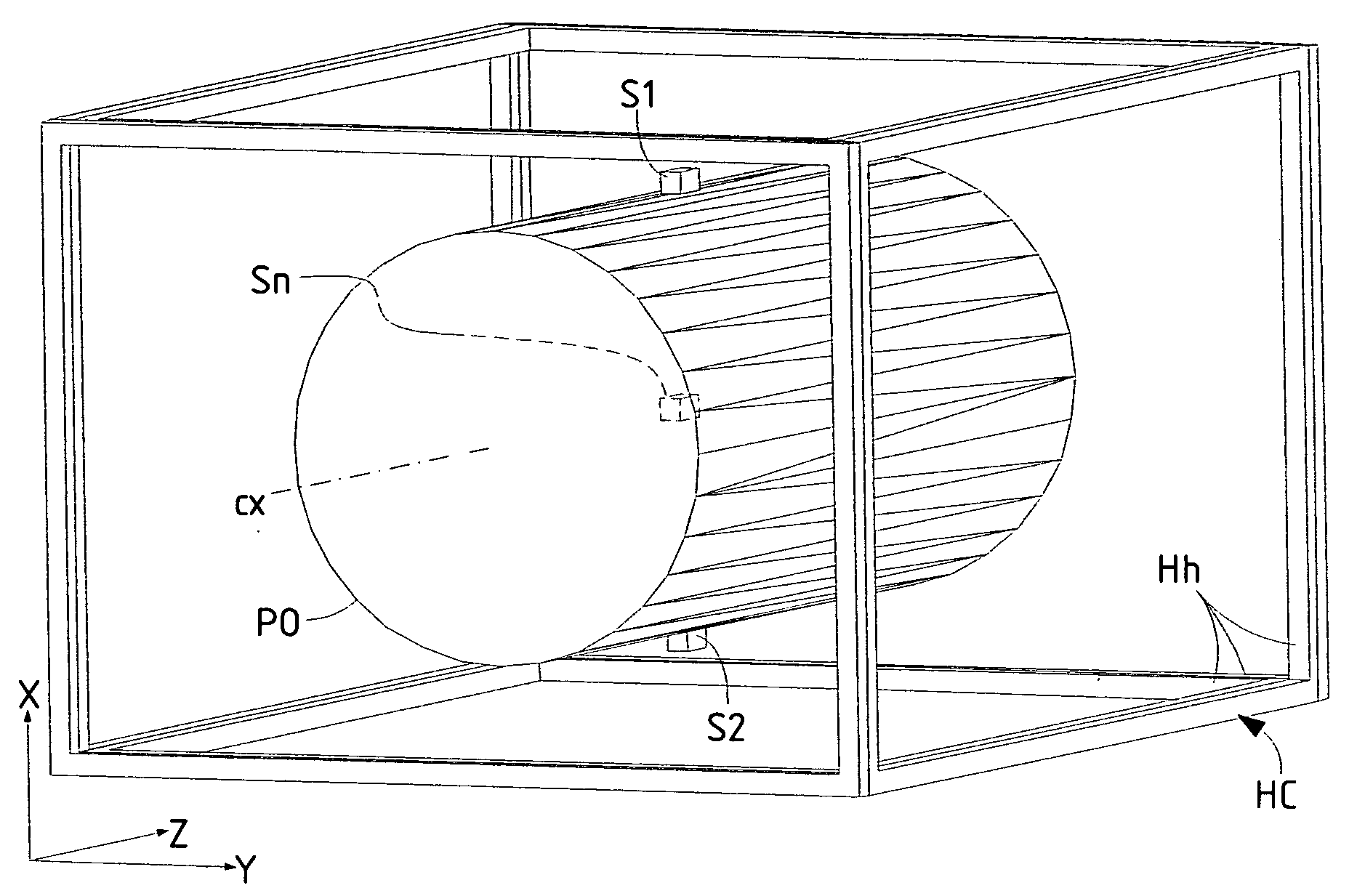
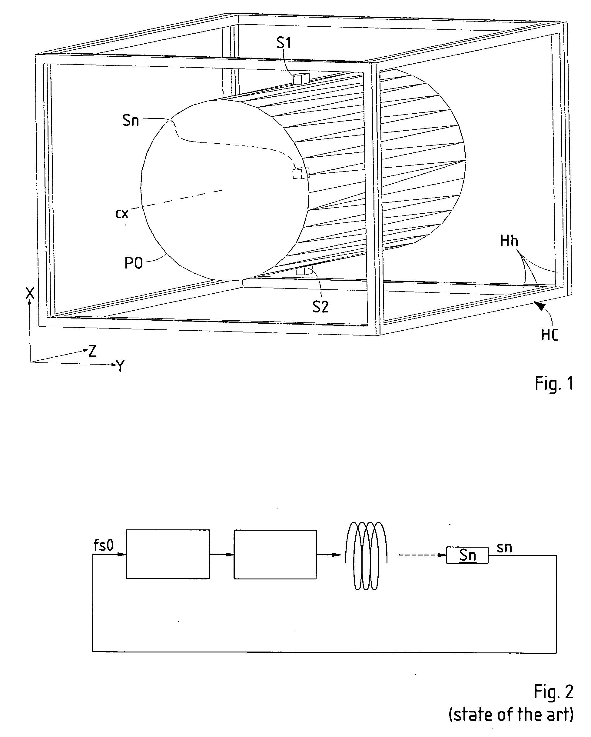
[0033] The magnetic field compensation system according to the invention has two flux sensors S1, S2. They are mounted symmetrically to the optical axis cx of the particle optical system PO and symmetrically to the Helmholtz coils of the cage HC (FIG. 1). Each flux sensor measures the flux in three components (Bx,By,Bz) of a Cartesian coordinate system whose axes coincide with the main axes of the Helmholtz cage HC. It is also possible, in a variant, to use two times three sensors for the field components Bx, By and Bz.

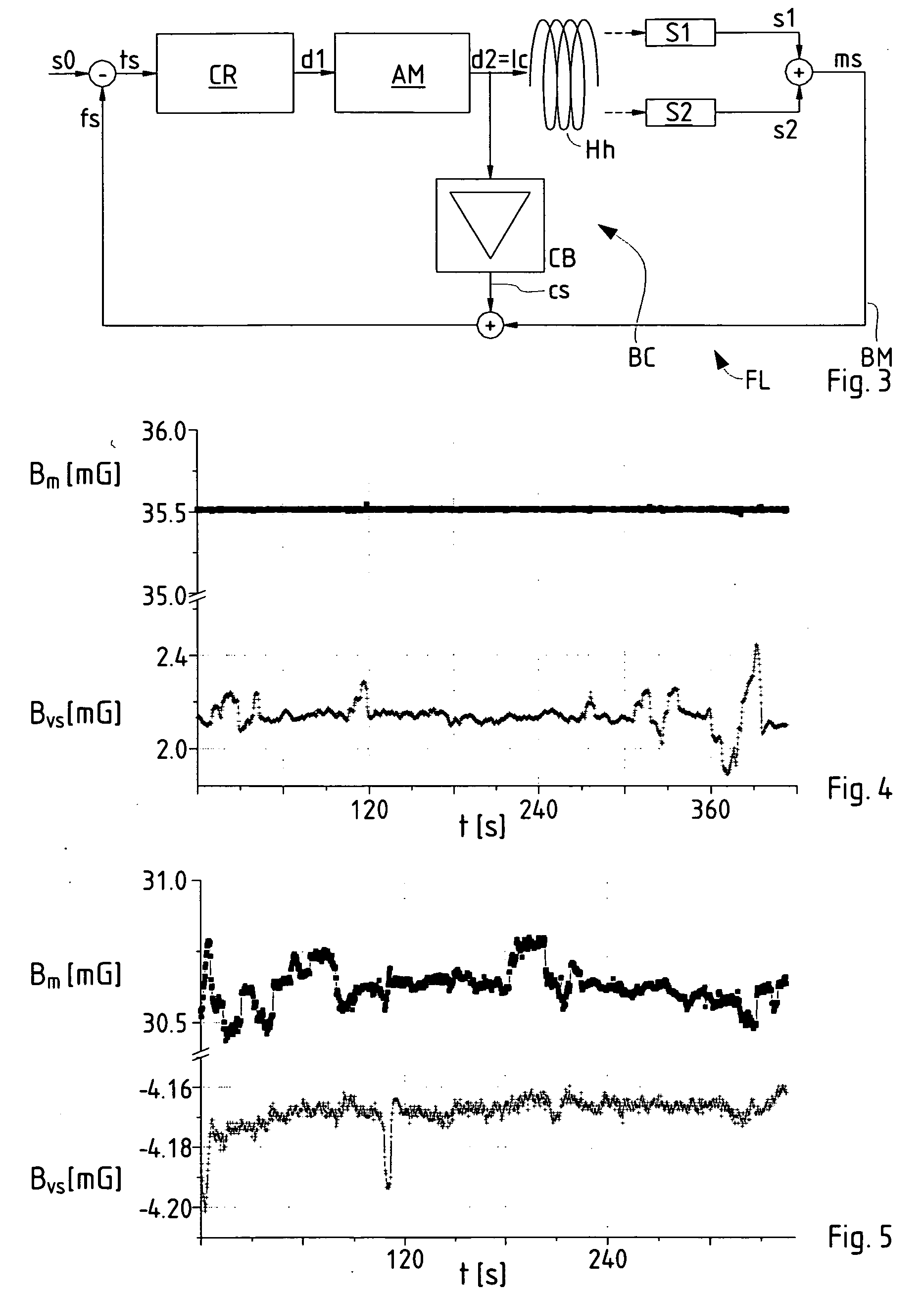
[0034]FIG. 3 shows the feedback loop FL according to the invention used for one of the field components, for instance the vertical component Bx; the total compensation system uses three loops as the one shown in FIG. 4. Each sensor S1, S...


PUM


Abstract

For compensation of a magnetic field in an operating region a number of magnetic field sensors (S1, S2) and an arrangement of compensation coils (Hh) surrounding said operating region is used. The magnetic field is measured by at least two sensors (S1, S2) located at different positions outside the operating region, preferably at opposing positions with respect to a symmetry axis of the operating region, generating respective sensor signals (s1, s2), the sensor signals of said sensors are superposed to a feedback signal (ms, fs), which is converted by a controlling means to a driving signal (d1), and the driving signal is used to steer at least one compensation coil (Hh). To further enhance the compensation, the driving signal is also used to derive an additional input signal (cs) for the superposing step to generate the feedback signal (fs).

Description

FIELD OF THE INVENTION AND DESCRIPTION OF PRIOR ART [0001] The invention relates to an improvement in the compensation of a magnetic field in a predefined operating region with feedback control, using magnetic field sensors and an arrangement of compensation coils surrounding said operating region. [0002] Many technical applications require surroundings well shielded from external magnetic fields. One example for an apparatus that requires a good compensation of magnetic fields is a particle-optical system such as electron microscopes or ion-beam exposure apparatus. In a system of this kind, a particle (electron or ion) beam is used traveling along a specific path and directed against a target to be imaged or structured, and any external magnetic field may deflect the particle beam off its path, thus deteriorating obstructing the performance of the device; this is the reason why a compensation of magnetic fields is needed. While a vacuum housing, which usually is made of aluminum or...

Claims


Application Information

Patent Timeline
IPC IPC(8): H01J37/20G05F7/00H01H47/00H01L21/027
CPCG05F7/00
Inventor BUSCHBECK, HERBERTSTENGL, GERHARD
Owner IMS NANOFABTION
Why Eureka
Try Eureka