Ad-hoc connection between electronic devices

a technology of electronic devices and connections, applied in the field of ad-hoc connection between electronic devices, can solve the problems of burden in actually using an available function and the challenge of connecting profiles, and achieve the effects of reducing user time, avoiding having to type through a menu structure, and improving usability of electronic devices

Active Publication Date: 2005-09-08
NOKIA TECHNOLOGLES OY
View PDF100 Cites 134 Cited by
  • Summary
  • Abstract
  • Description
  • Claims
  • Application Information

AI Technical Summary

Benefits of technology

[0018] It is an advantage of the invention that it allows to unify the user experience of setting up a local or non-local ad-hoc connection across different technologies between electronic devices which are close to each other. If in wide use, the invention even allows unification of the user experience of setting up such a connection across all or almost all electronic devices that a person may own or use.
[0019] It is further an advantage of the invention that it reduces the amount of user time needed to set up such a connection. The invention makes setting up an ad-hoc connection and using it for a specific purpose a very intuitive, physical and easy experience, as it allows one to avoid having to type through a menu structure. Thus, it improves the usability of electronic devices.
[0020] In one embodiment of the invention, a hugging state is assumed to be given if the first and the second electronic devices actually touch each other physically. In order to enable a detection of such a touch, the electronic devices may be provided on their surface with a material ensuring a galvanic contact, for example a metal or a polymer that conducts electricity. A hugging state may also be seen in the act of connecting two devices, for example if a data cable is connected between a mobile phone and PC constituting the electronic devices, an Internet Protocol (IP) connection is opened, a VPN tunnel is set up and a http GET is done. For instance, a user could connect a desktop computer and a media phone with a data cable for one second and then leave the room taking the media phone along.
[0021] As an alternative to touching, a hugging state may also be assumed to be given for example if one electronic device, in particular a mobile device, is used for pointing at another electronic device. Such a pointing can be detected for instance by means of an infrared beam, a laser light or an infrasound, which all support passing information for a handle.
[0022] As a further alternative to touching, a hugging state may be assumed to be given if one electronic device is brought into close proximity of another device, for example to a distance of 5 to 50 centimeters. Detecting the proximity of another device can be based on the same technologies as detecting a pointing, if means for measuring the distance are added to the electronic devices. In addition, purely non-directional signals, such as those used in WLAN, Bluetooth™ or Radio Frequency Identification (RFID), can be used. At least Bluetooth™ enables a measurement of the distance. More specifically, the distance can be derived from Receive Signal Strength Indicator (RSSI) measurements.
[0023] The physical means required for detecting a hugging state thus depend on the respectively supported type or types of hugging which shall be detected. They may comprise a galvanic surface, an infrared (IR) led / detector, an RFID chip, a Bluetooth™ chip, etc. The physical means can be part of an electronic device itself or be built into an accessory, such as snap-on covers of a mobile phone. In addition, a logic can be used to determine that a hugging is taking place based on the information provided by the physical means.

Problems solved by technology

Finding the necessary parameters for the connection profile is a challenge of its own.
This requires a couple of steps, and for many technically inexperienced end users, this will be a burden in actually using an available function.

Method used


Image

  • Ad-hoc connection between electronic devices
  • Ad-hoc connection between electronic devices
  • Ad-hoc connection between electronic devices

Examples


first embodiment

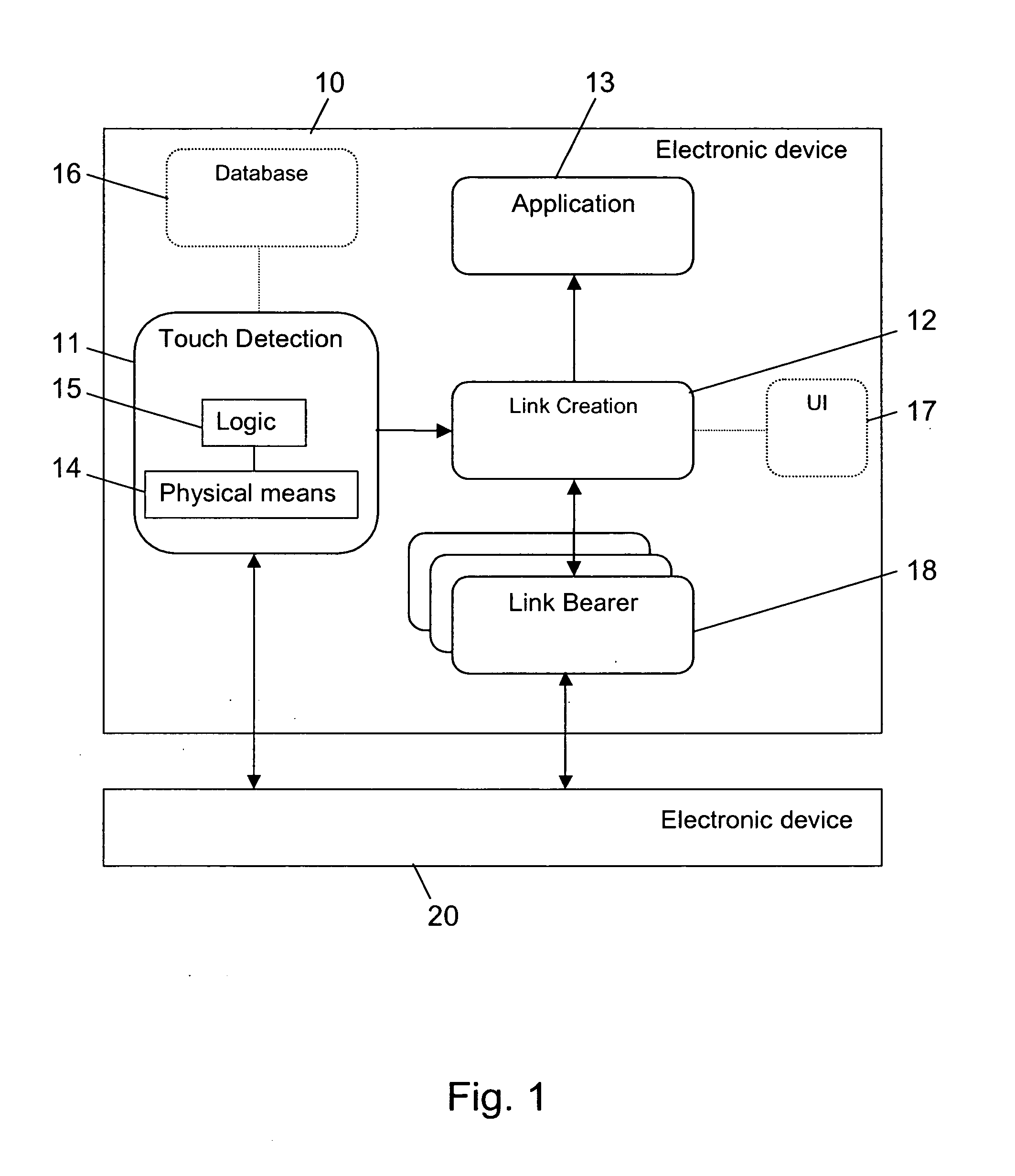
[0096]FIG. 1 schematically presents a block diagram with two electronic devices 10, 20, which are enabled to create a hugging-based ad-hoc connection between each other in accordance with the invention. At least one of the electronic devices is a mobile device.

[0097] The first electronic device 10 comprises a touch detection portion 11, a link creation portion 12 and at least one application 13. The touch detection portion 11 further comprises physical means 14 for realizing the hugging and a logic 15. The touch detection portion 11 may further have access to a local database 16, as indicated in FIG. 1 by dotted lines. The database 16 maps known RFIDs to usable IP addresses. Moreover, a user interface 17 may be connected to the link creation portion 12, which is equally indicted by dotted lines. In the current embodiment, the physical means 14 for hugging include by way of example by an RFID chip, which is integrated into the electronic device 10. The link creation portion 12 has ac...

second embodiment

[0122]FIG. 3 schematically presents a block diagram with two electronic devices 30, 40, which are enabled to create a hugging-based ad-hoc connection between each other in accordance with the invention. At least one of the electronic devices is a mobile device.

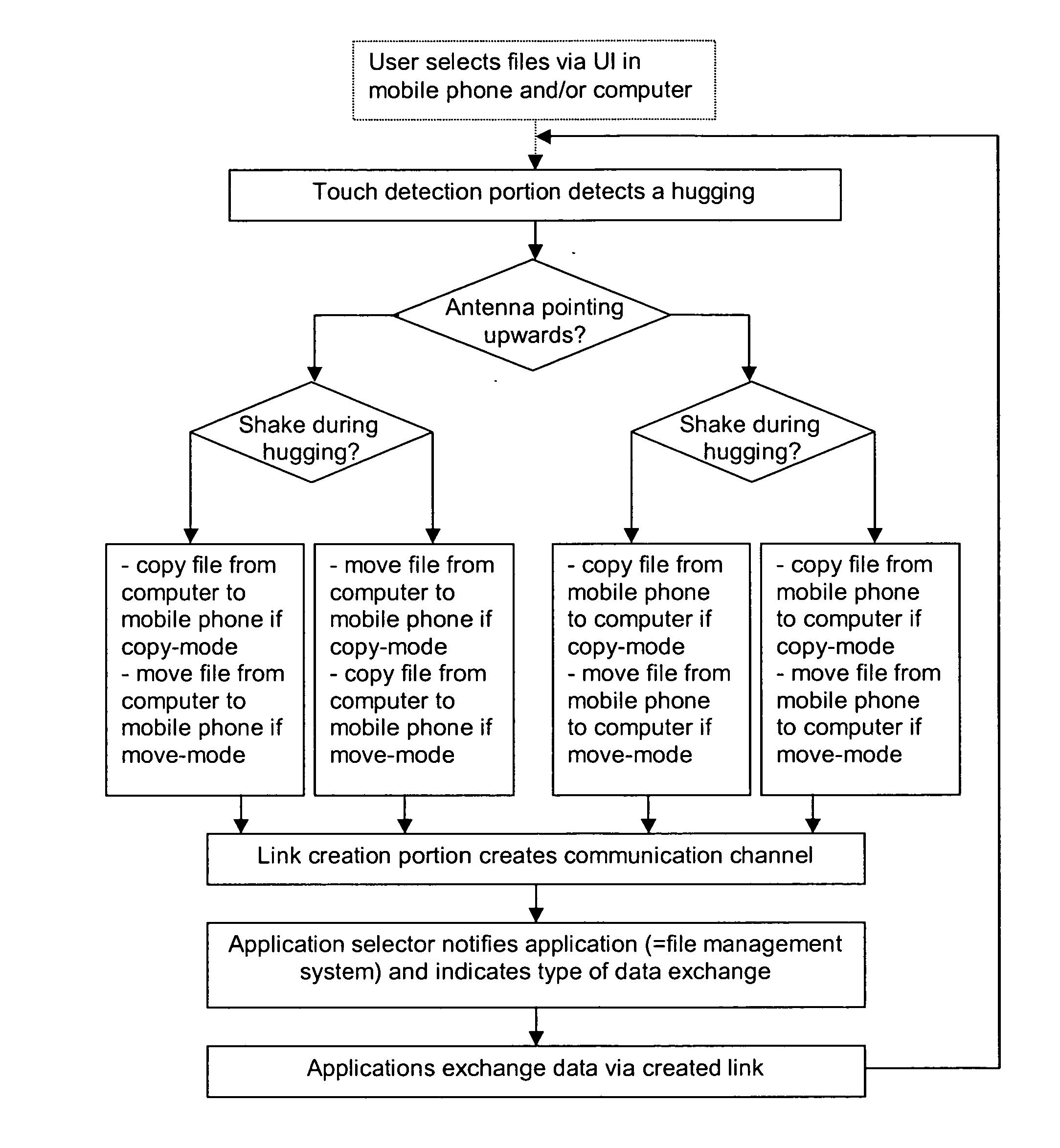
[0123] The first electronic device 30 comprises components 31 to 38 which correspond to the components 11 to 18 of the first electronic device 10 of FIG. 1. In addition, however, it comprises an application selector 39 arranged between the link creation portion 32 and a plurality of applications 33.

[0124] For the second electronic device 40, no details are shown. It is assumed to comprises the same components as the first electronic device 30, even though some components could be missing.

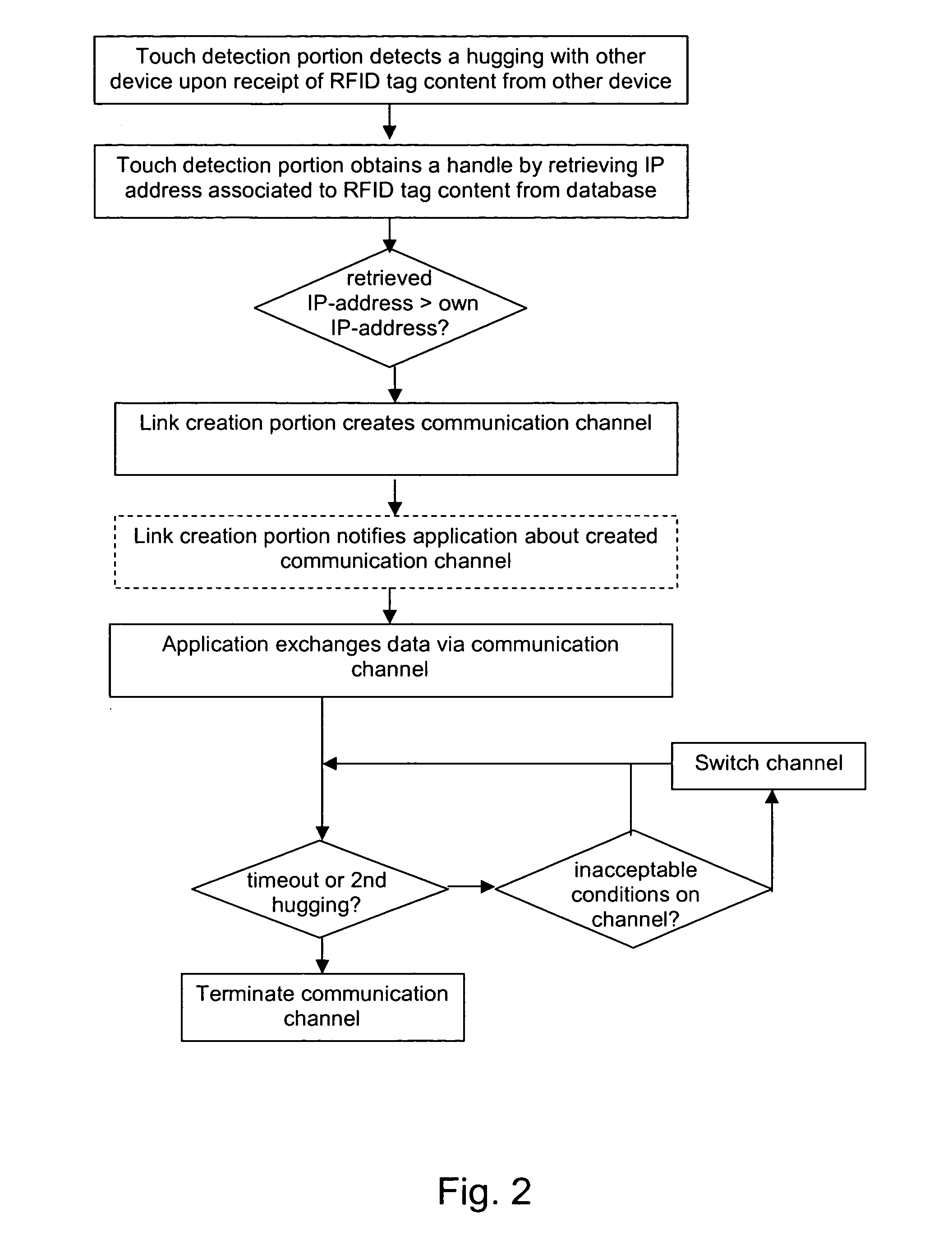
[0125] The creation of an ad-hoc connection between the first electronic device 30 and the second electronic device 40 of FIG. 3 will now be described with reference to the flow chart of FIG. 4.

[0126] The creation of the ad-hoc connection i...

third embodiment

[0137]FIG. 5 schematically presents an electronic device, which is enabled to create a hugging-based ad-hoc connection with another electronic device in accordance with the invention.

[0138] The electronic device 50 comprises in contrast to the embodiments of FIGS. 1 and 3 an extendable framework with partly variable functional blocks.

[0139] The framework comprises like the electronic devices of FIGS. 1 and 3 a touch detection portion 51, a link creation portion 52 with access to link bearers 58 and applications 53. In addition, however, it comprises an additional control logic portion 60 which is responsible for enforcing the logic needed to provide additional services which a particular implementation of the electronic device 50 may provide to the applications 53 in the device 50 or in other devices, or to the implementation in general of other devices.

[0140] The touch detection portion 51, the link creation portion 52 and the applications53 have access to the additional control ...


PUM


Abstract

The invention relates to a method of creating an ad-hoc connection between two electronic devices. In order to enable a particularly user-friendly creation of such a connection, it is proposed that a first device detects a hugging state between the first device and a second device, in which the first device and the second device are in close vicinity and a piece of information is received at the first device directly from the second device. In case a hugging state is detected, a handle is obtained proceeding from the received piece of information. The handle comprises an address of some device other than the first device. Finally, a communication channel is established between the first device and the other device using the address included in the handle. The invention relates equally to a corresponding device, to an expandable framework for such a device, and to a corresponding software program product.

Description

FIELD OF THE INVENTION [0001] The invention relates to a method of creating an ad-hoc connection between at least two electronic devices for enabling an interaction between the at least two electronic devices. The invention relates equally to a corresponding device and to a corresponding software program product. BACKGROUND OF THE INVENTION [0002] A mobile electronic device often travels along with its user from place to place. Each day, the user encounters dozens or even hundreds of other electronic devices having the potential to communicate with the mobile electronic device. The user meets for instance other people-carrying their own mobile electronic devices, visits places equipped with consumer or office electronics, or passes by a store that provides electronic services or marketing. [0003] There exist powerful user interface (UI) concepts which can be used in communications between different electronic devices, such as cut-and-paste, copy-and-paste and drag-and-drop concepts....

Claims


Application Information

Patent Timeline
Patent Type & Authority Applications(United States)
IPC IPC(8): H04L12/28H04L12/56H04M1/72412
CPCH04M1/7253H04W4/206H04W8/26H04L41/22H04W76/02H04W84/18H04W24/00H04W4/21H04W76/10H04M1/72412G06F3/048
Inventor POHJA, SEPPOHIETASARKA, JUHAHUSSMANN, HOLGER
Owner NOKIA TECHNOLOGLES OY
Why Eureka
Try Eureka