Briaud compaction device

a compaction device and compaction technology, applied in the field of soil compaction testing equipment and methods, can solve problems such as improper orientation of the test device by users, and achieve the effect of simple and effective device and techniqu

Inactive Publication Date: 2005-09-15
TEXAS A&M UNIVERSITY
View PDF15 Cites 9 Cited by
  • Summary
  • Abstract
  • Description
  • Claims
  • Application Information

AI Technical Summary

Benefits of technology

[0008] The invention provides a simple and effective device and technique for determining soil modulus, and, in turn, soil compaction. An exemplary compaction testing device is described that includes a ground contacting plate that is interconnected by a rigid rod to a measurement module. The measurement module includes a load cell assembly for determining the compressive force placed upon the rigid rod. The ground contacting plate is provided with a number of strain sensors that detect hoop and radial strain in the plate. The sensors provide the detected strain data to the measurement module. Additionally, the measurement module includes a processor to receive the detected strain data from the strain sensors and load measurements from the load cell. The processor is programmed with models or relationship that use the measured data to determine the soil modulus. The measurement module also provides a display device to provide readings to a user for the above measured parameters and calculated soil modulus. A gripping handle is provided on the measurement module for applying downward force to the rigid rod and plate.
[0011] As noted earlier, embodiments suitable for hand-held use can include a tubular member such as a rod to connect the control member to the measurement module. During manual operation, the user may not orient the test device properly relative to the soil surface. To minimize the damage to the test device or errors in the measurements resulting from misalignment attributable to this and other sources, an articulated joint such as a ball joint can be used to couple the tubular member to the control member. Additionally, a pliant pad can be mated or fixed to a face of the control member to equalize or distribute the pressure applied by the plate to the soil surface.

Problems solved by technology

During manual operation, the user may not orient the test device properly relative to the soil surface.

Method used


Image

  • Briaud compaction device
  • Briaud compaction device
  • Briaud compaction device

Examples


Embodiment Construction

[0020] The present invention relates to devices and methods for determining soil compaction. The present invention is susceptible to embodiments of different forms. Shown in the drawings and described in detail are specific embodiments of the present invention with the understanding that the present disclosure is to be considered an exemplification of the principles of the invention, and is not intended to limit the invention to that illustrated and described herein.

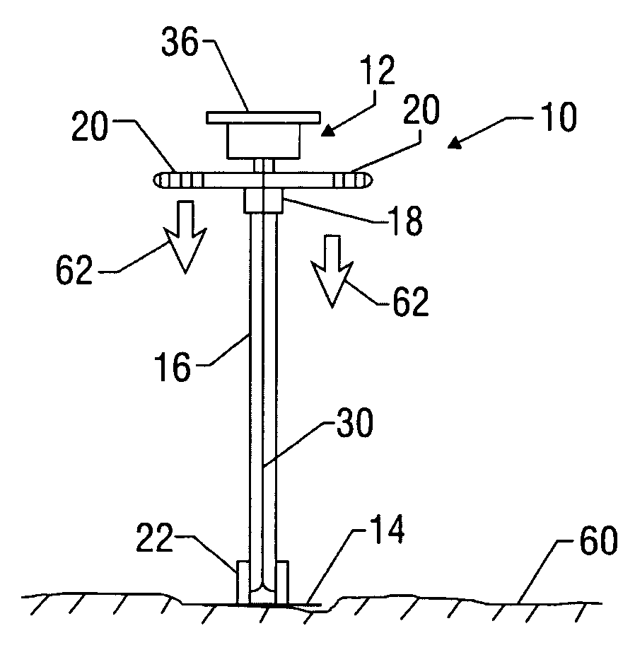
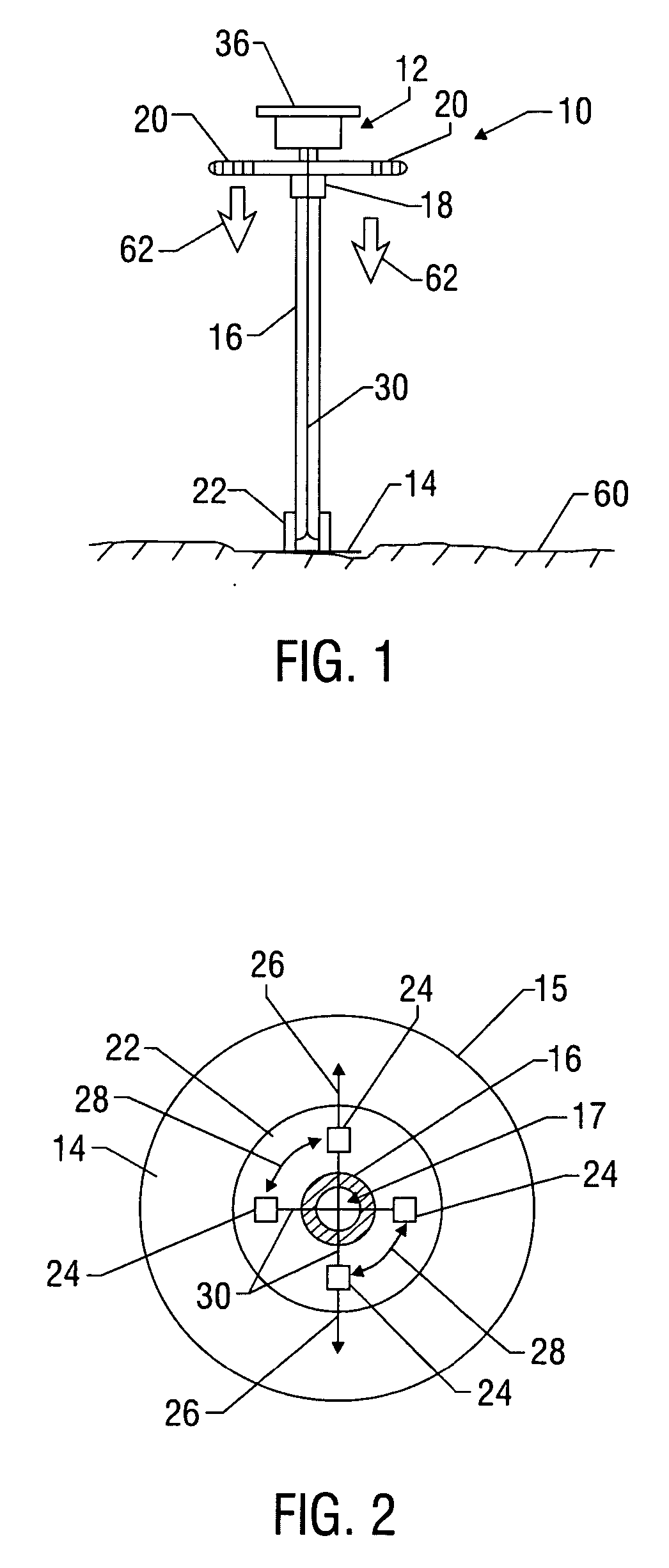
[0021]FIGS. 1 and 2 illustrate an exemplary soil compaction testing device 10 constructed in accordance with the present invention. The testing device 10 is lightweight and portable, intended to be easily carried and operated by a single person. The testing device 10 includes a measurement module, shown generally at 12; a ground-contacting plate 14; and a tubular member 16 that interconnects the plate 14 with the measurement module 12. The tubular member 16 can be a relatively rigid rod having a bore for accommodating d...


PUM

PropertyMeasurementUnit
diameteraaaaaaaaaa
thicknessaaaaaaaaaa
soil modulusaaaaaaaaaa

Abstract

A device for determining soil compaction includes a control member fitted with one or more sensors that measure the response of the control member during co-action between the control member and a soil surface. In one embodiment, this response can be flexure as characterized by a measurable parameter such as strain. A measurement module in communication with the sensor or sensors determines a soil modulus for the soil based on the strain measurement from the sensor or sensors. In one arrangement, the control member includes one set of sensors that measure radial strain and another set of sensors that measures hoop strain. The device can also include a load sensor for measuring the load applied to the control member. In one embodiment the measurement module includes a processor that determines soil modulus based the strain measurements and the measured load.

Description

CROSS-REFERENCE TO RELATED APPLICATIONS [0001] This application takes priority from U.S. Provisional Application Ser. No. 60 / 549319, Filed Mar. 2, 2004.BACKGROUND OF THE INVENTION [0002] 1. Field of the Invention [0003] The invention relates generally to soil compaction testing equipment and methods for testing the compaction of soils. In particular aspects, the invention relates to devices and methods for determining the soil modulus of soil. [0004] 2. Description of the Related Art [0005] Traditionally, techniques for controlling and monitoring the degree of compaction for soils have involved the measurement of dry density for the soil and the determination of an optimum water content for the soil. The term “soil,” as used herein, is intended to apply to a wide variety of substances that are intended to be compacted to a specific degree of density in the course of typical civil construction works, including natural soil, base courses, asphalt, embankments and retaining wall backfi...

Claims


Application Information

Patent Timeline
Patent Type & Authority Applications(United States)
IPC IPC(8): G01N3/30
CPCE02D1/08G01N33/24G01N3/40
Inventor BRIAUD, JEAN-LOUISBRIAUD, PATRICKLI, YANFENGFAWCETT, ANDREWPOTTER, MATTHEW L.
Owner TEXAS A&M UNIVERSITY
Why Eureka
Try Eureka