
Electric steering apparatus for watercraft

a technology for watercraft and steering apparatus, which is applied in the direction of steering initiation, special purpose vessels, vessel construction, etc., can solve the problems of operator unaware of any such load, operator cannot feel external forces, and operator does not provide feedback for

Inactive Publication Date: 2005-09-15
YAMAHA MARINE KK
View PDF3 Cites 46 Cited by
  • Summary
  • Abstract
  • Description
  • Claims
  • Application Information

AI Technical Summary

Benefits of technology

[0012] An aspect of at least one of the embodiments disclosed here and includes a realization that providing feedback or reaction forces to the steering wheel of a watercraft allows the operator of the watercraft to respond more quickly to imminent course changes of the watercraft. Further, additional advantages are achieved where certain forces exerted on the watercraft are filtered and thus not transmitted to the steering wheel as feedback.

Problems solved by technology

With such an electric steering apparatus, however, no feedback force is provided to the operator.
For example, when wind or other water currents exert loads on the outboard motor, the operator is unaware of any such loads.
Thus, the operator cannot feel those external forces which can manifest themselves as a heavy or light feel of the steering wheel during operation.
As such, the operator is less able to respond to such loads and thus is less able to quickly respond to such loads.
This results in a continuous power consumption by the electric motor at all times.
Further, the technique disclosed in JP-B-2959044 does not compensate for the lack of feedback feeling in the steering wheel, nor does it describe a system that can provide reaction forces at the steering wheel.
Thus, with the system and technique disclosed in the JP-B-2959044 patent, it is impossible to obtain an operating feeling depending on the steering wheel operation or a driving feeling through the steering wheel.
Thus, it is difficult to recognize imminent course changes that may result from the waves, wind or the paddle-rudder effect and to quickly respond to these forces to maintain a desired course.
This control technique for automobiles is not simply applicable to boats, which receive a force due to the paddle-rudder effect described above, as well as other effects.

Method used


Image

  • Electric steering apparatus for watercraft
  • Electric steering apparatus for watercraft
  • Electric steering apparatus for watercraft

Examples


Embodiment Construction

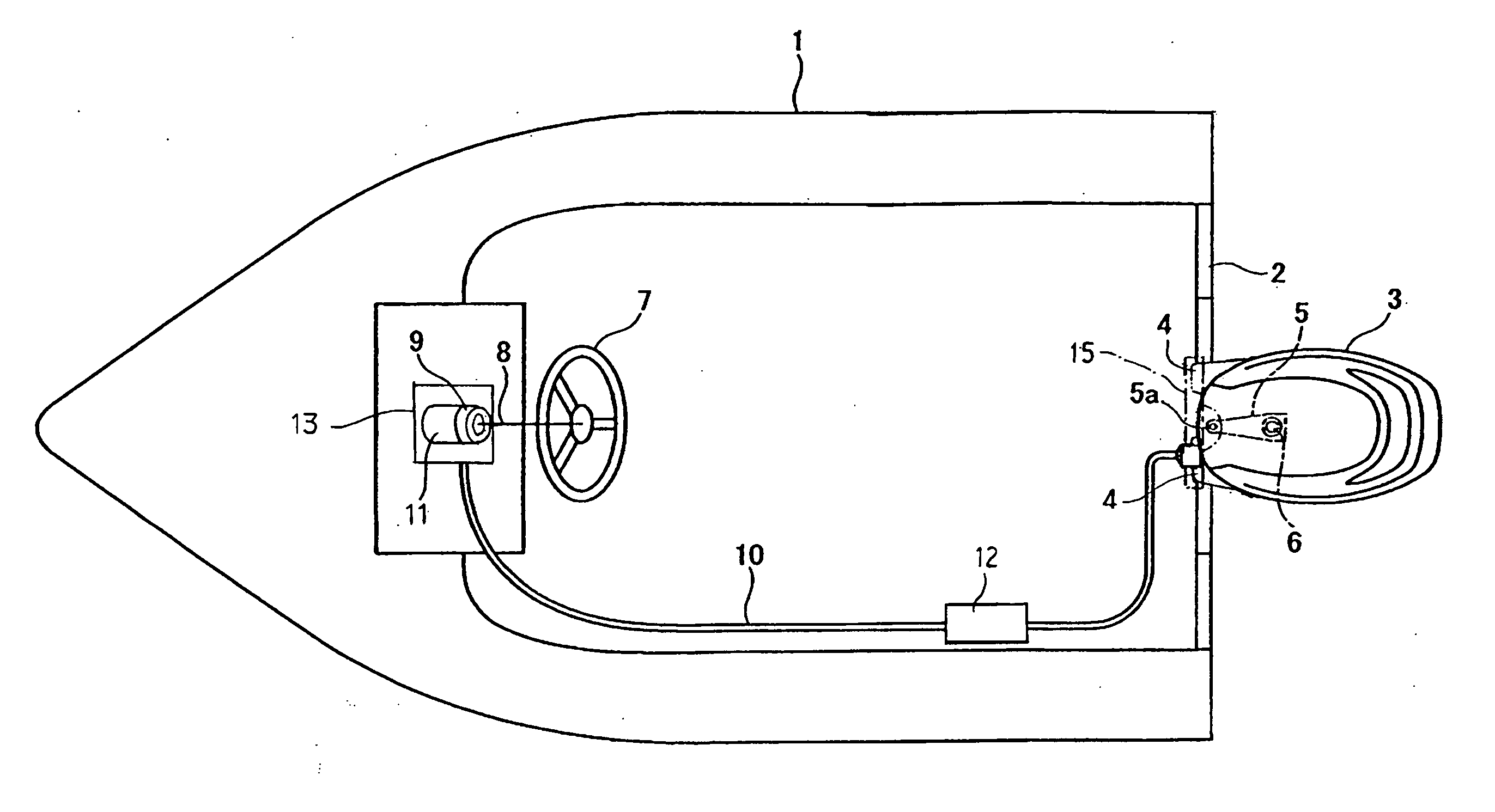
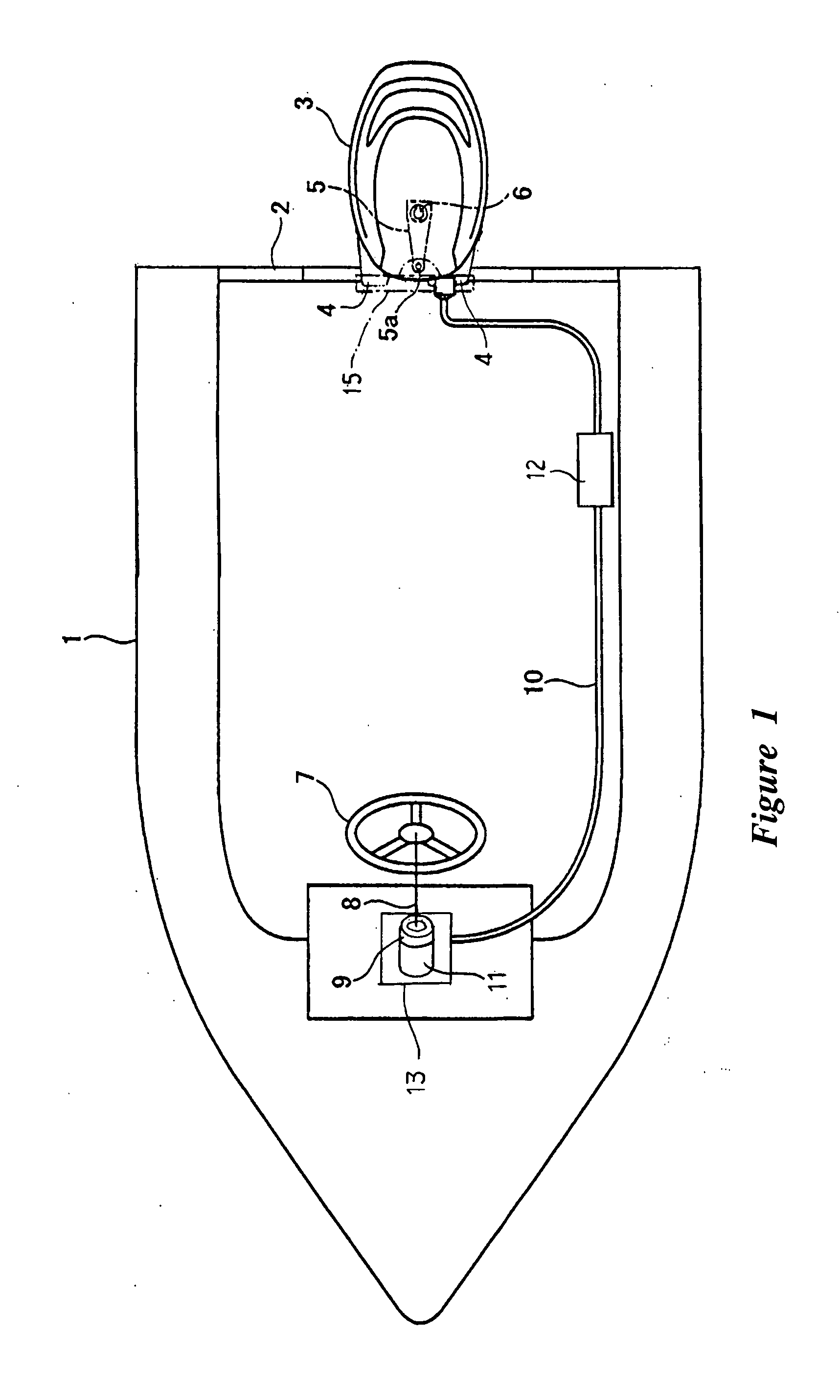
[0021]FIG. 1 is a schematic top plan view of a small boat or watercraft, including an outboard motor with which the present embodiments are applicable. The embodiments disclosed herein are described in the context of a marine propulsion system having an electric steering system for a small boat because these embodiment have particular utility in this context. However, the embodiments and inventions herein can also be applied to other marine vessels with stern drives, personal watercraft, small jet boats, as well as other vehicles.

[0022] With reference to FIG. 1, an outboard motor 3 can be mounted to a transom plate 2 of a hull 1 of a small boat or watercraft with clamp brackets 4. As used herein, the terms “small boat” and “watercraft,” are used interchangeably.

[0023] The outboard motor 3 is mounted to be rotatable about a swivel shaft (or “steering shaft”) 6. A steering bracket 5 is fixed to an upper end of the swivel shaft 6.

[0024] A rudder device 15 can be connected to an end ...


PUM


Abstract

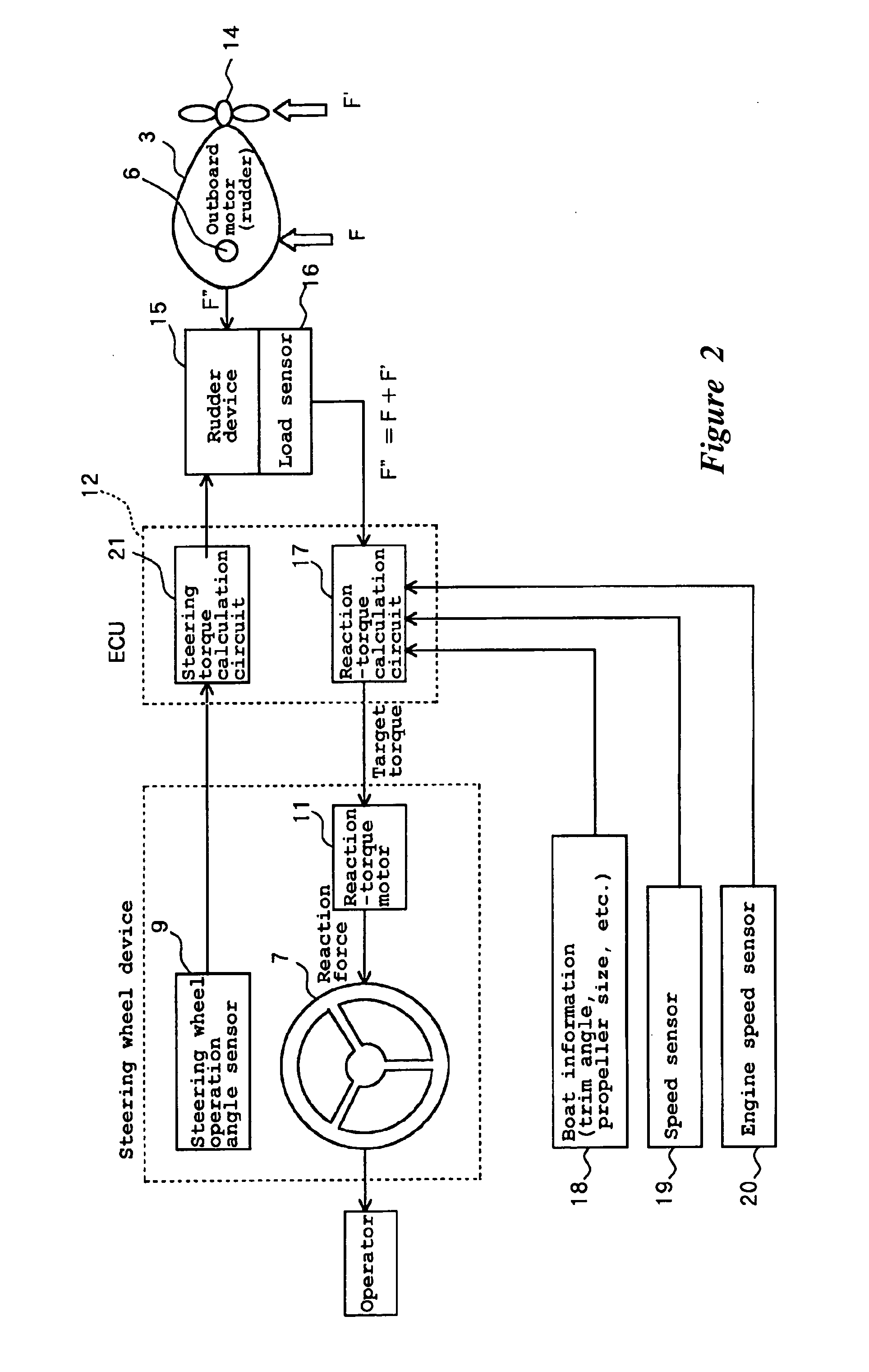
An electric steering apparatus can include a rudder device driven by an electric motor, a steering wheel for operation by an operator to control the angle of the rudder device, a reaction torque motor for applying a reaction force to the steering wheel, a load sensor for detecting an external force acting on a boat or the rudder during steering, and a reaction torque calculator circuit for calculating a target torque for the reaction motor according to an input of the load sensor.

Description

PRIORITY INFORMATION [0001] This application is based on and claims priority to under 35 U.S.C. § 119 to Japanese Patent Application No. 2004-065689 filed Mar. 9, 2004, the entire contents of which is hereby expressly incorporated by reference. BACKGROUND OF THE INVENTION [0002] 1. Field of the Invention [0003] The present inventions relate to an electric steering system for a small boat, and in particular, to steering systems that provide variable steering response. [0004] 2. Description of the Related Art [0005] Japanese Patent No. JP-B-2739208 discloses an electric steering apparatus for watercraft using an electric motor for changing the steering angle of an outboard motor. The electric steering apparatus disclosed therein includes a sensor for detecting the rotational angle and direction of operation of a steering wheel, as well as a controller for controlling the electric motor of the steering device based on a detection signal from the sensor. The steering wheel is electronic...

Claims


Application Information

Patent Timeline
IPC IPC(8): B63H25/42B63H20/00B63H20/12B63H25/00B63H25/02B63H25/24
CPCB63H20/12B63H25/24B63H25/02B63H2025/022
Inventor MIZUTANI, MAKOTO
Owner YAMAHA MARINE KK
Learn More