Fireplace hydronic heating

a hydronic heating and fireplace technology, applied in the direction of heating types, ways, stoves or ranges, etc., can solve the problems of unfavorable fireplace functions, damage to the building structure, and unfavorable fireplace functions, so as to improve the manufacturability of the hydronic heating system and eliminate condensation

Inactive Publication Date: 2005-09-15
HNI TECH INC
View PDF51 Cites 7 Cited by
  • Summary
  • Abstract
  • Description
  • Claims
  • Application Information

AI Technical Summary

Benefits of technology

[0008] The present invention generally relates to hydronic heating systems, and more particularly relates to fireplace hydronic heating systems that are designed to eliminate condensation and improve manufacturability of the hydronic heating system.

Problems solved by technology

A common problem associated with fireplace hydronic heating systems is undesired condensation buildup on the structure holding the liquid due to the temperature differential between the cool liquid and the heated air generated by the fireplace.
This condensation is aesthetically undesirable and may adversely effect functions of the fireplace.
Further, if the condensation occurs on the outside of the combustion chamber enclosure, for example within an interior wall of the building in which the fireplace is mounted, the condensation may result in damage to the building structure.

Method used


Image

  • Fireplace hydronic heating
  • Fireplace hydronic heating
  • Fireplace hydronic heating

Examples


example

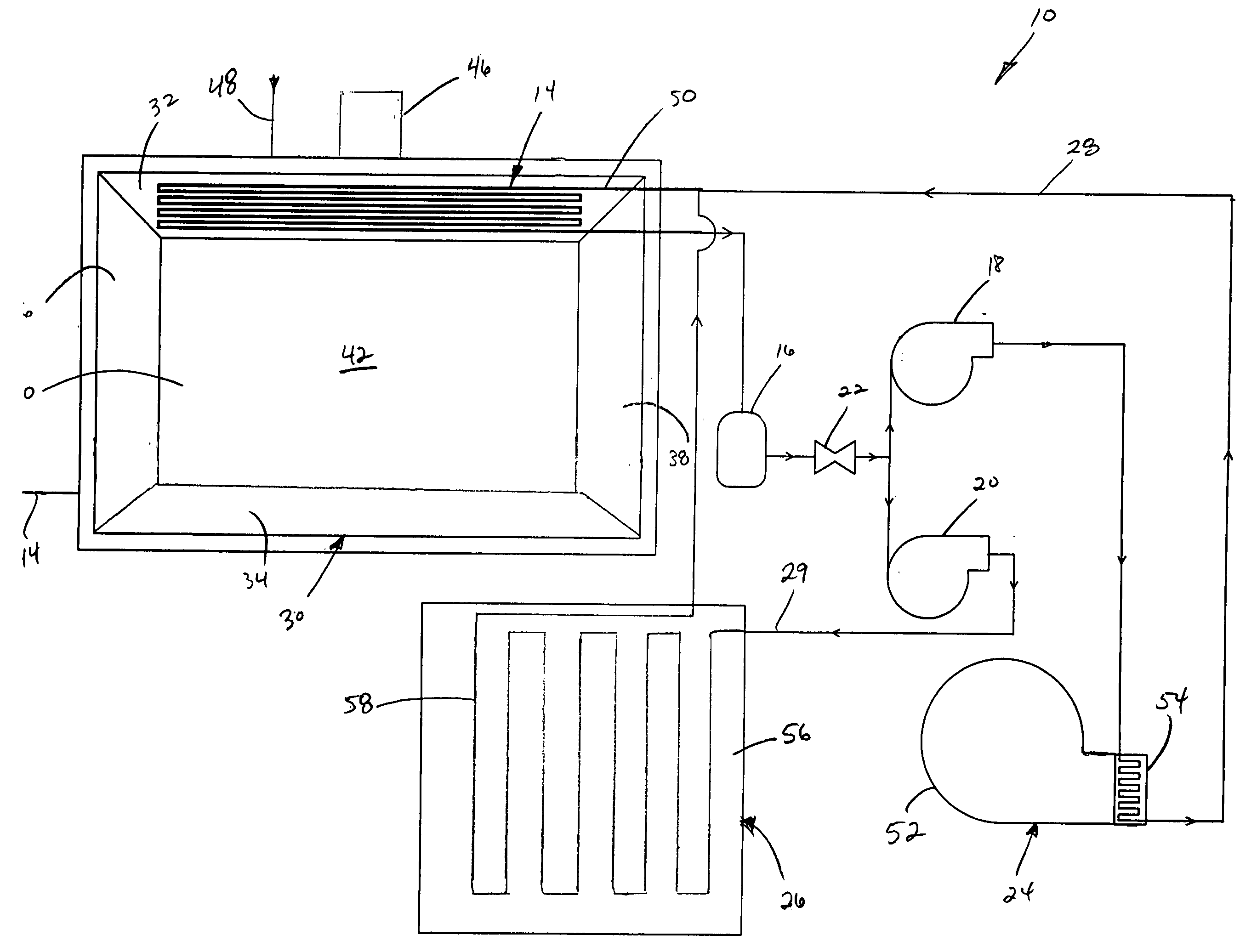
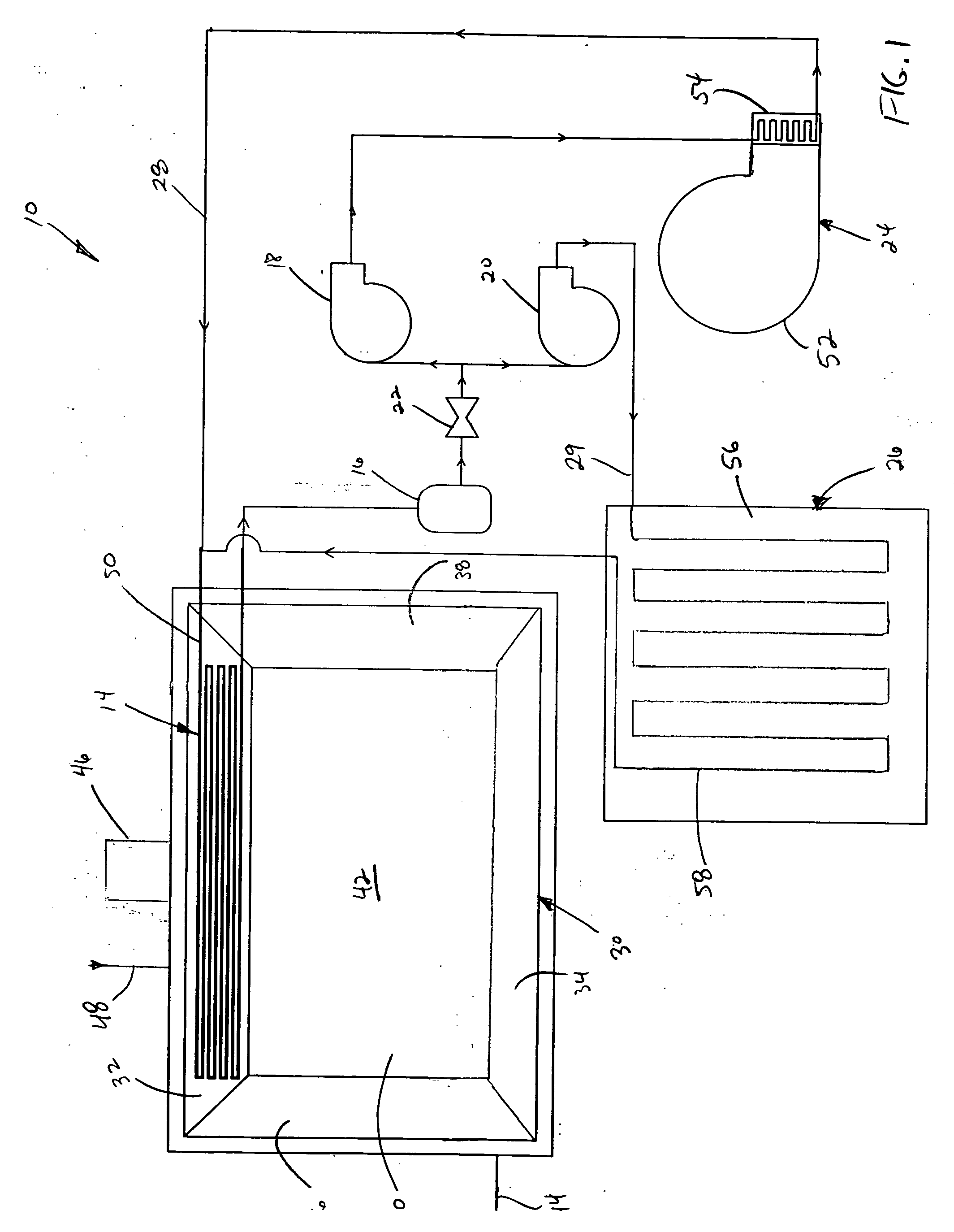
[0031] In an example hydronic heating system application, the heating system is used to heat a 1,500 square foot room having 8 foot ceilings and a cement floor. Liquid-filled conduits are embedded in the cement floor and coupled to liquid-filled conduits embedded in a panel of a combustion chamber enclosure of the heating appliance. The liquid being heated in the hydronic heating system is a mixture of about 50% water and 50% glycol and is carried in half-inch HEPEX™ tubing between the heating appliance and the cement floor. The desired temperature of the air in the room is 70° F. and the temperature outside of the room is 11° F. In order to heat the room to the desired temperature, the heating appliance generates about 13,300 BTUs / hour to generate a liquid temperature in the liquid-filled conduits of the combustion chamber enclosure of about 80° F. The heated liquid is pumped to the liquid-filled conduits of the cement floor at a flow rate of about 2.9 gal / min to heat the cement fl...


PUM


Abstract

A hydronic heating system that includes a liquid-filled conduit and a combustion chamber enclosure having a plurality of panels that define a combustion chamber for the combustion of fuel to generate heat. At least one of the panels and a portion of the liquid-filled conduits are integrally formed together. The at least one panel absorbs heat generated in the combustion chamber and transfers the absorbed heat to the liquid in the conduit. The heated liquid may be transferred to a remote location where the heat is removed from the liquid using a heat exchanger. The at least one panel and the portion of the liquid-filled conduit may be integrally formed using a moldable material such as a ceramic fiber and a binder, and molded using such processes as compression molding or vacuum molding. The use of moldable may reduce condensation in or around the combustion chamber enclosure.

Description

BACKGROUND OF THE INVENTION [0001] 1. Field of the Invention [0002] The present invention generally relates to hydronic heating systems, and more particularly relates to hydronic heating systems that include a fireplace as a source of heat. [0003] 2. Related Art [0004] The use of closed loop liquid systems for the purpose of transferring heat generated within a heating appliance to a remote location for radiant convection of a surrounding area is well-known in the art. Liquid-based heating systems can be more efficient than air-based heating systems in many cases and may be particularly useful for scavenging otherwise lost heat from an existing air-based heating system. Liquid-based heating systems are often referred to as hydronic heating systems and typically include a liquid-filled conduit positioned next to a source of heat whereby the heat is absorbed into the liquid, the heated liquid is transferred to a remote location, and the heat is removed from the liquid at the remote lo...

Claims


Application Information

Patent Timeline
Patent Type & Authority Applications(United States)
IPC IPC(8): F24B1/183F24B1/188F24D3/00F24D7/00F24H1/22
CPCF24B1/1881F24D2200/10F24D2200/18F24D2220/2081Y02B10/70
Inventor BUTLER, GARY LEEBACHINSKI, THOMAS J.LYONS, DAVID CHARLES
Owner HNI TECH INC
Why Eureka
Try Eureka