
Apparatus and method for incision-free vaginal prolapse repair

a vaginal prolapse and permanent repair technology, applied in non-surgical orthopedic devices, obstetrical instruments, other nursing devices, etc., can solve the problems of complete eversion of the vagina, protrusion of vaginal tissue outside the vaginal opening, and breakage of support structures within the pelvis, so as to achieve minimal invasiveness, simple effect and low cos

Inactive Publication Date: 2005-09-15
KARRAM MICKEY M
View PDF5 Cites 151 Cited by
  • Summary
  • Abstract
  • Description
  • Claims
  • Application Information

AI Technical Summary

Benefits of technology

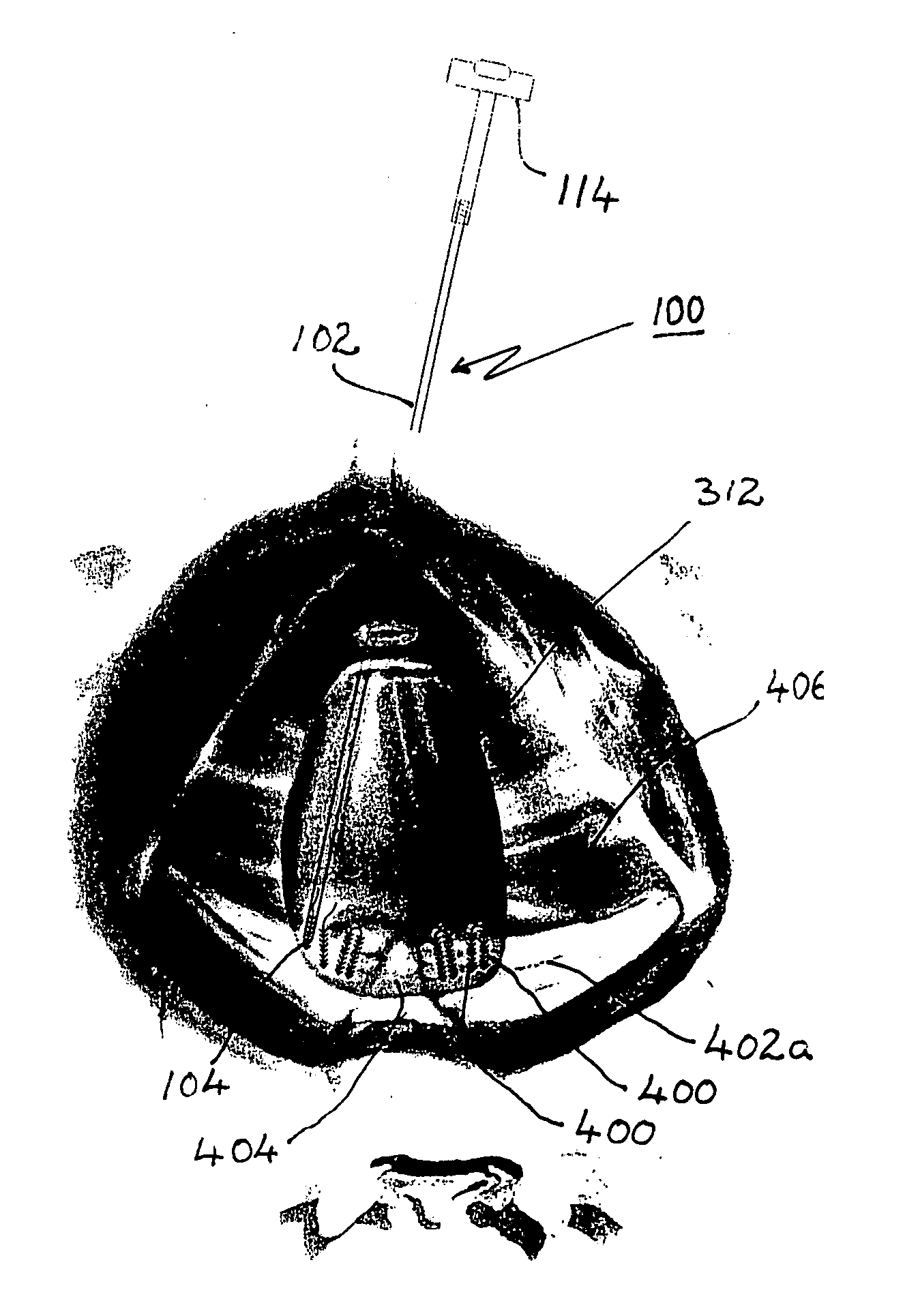
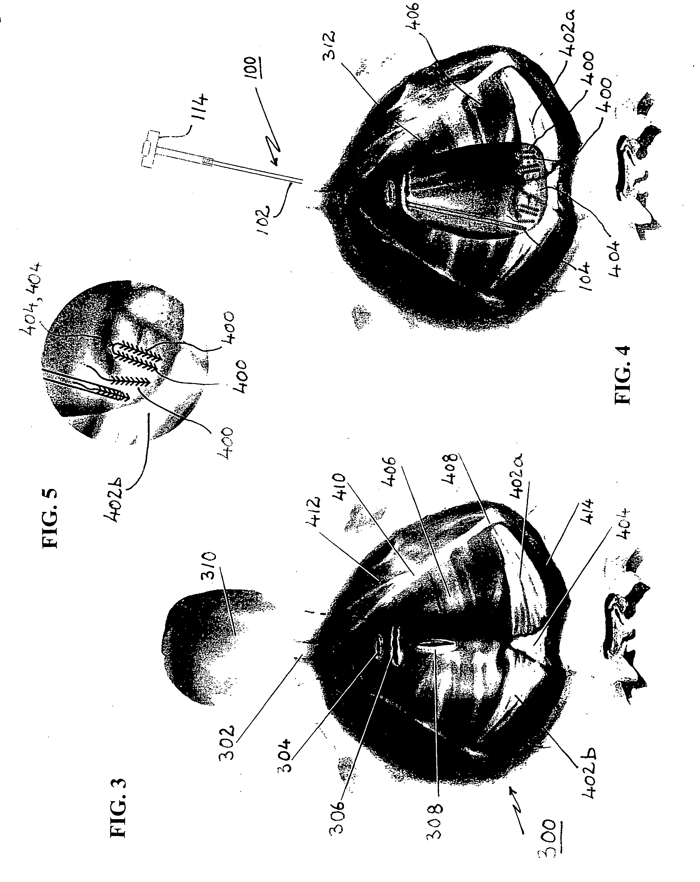
[0012] It is a principal object of this invention to provide a simple, minimally invasive and inexpensive apparatus for effecting vaginal prolapse repair without vaginal or abdominal incisions.
[0013] Another object is to provide a simple, minimally invasive and inexpensive apparatus by which a surgeon can quickly, relatively painlessly, affordably, safely and permanently repair a prolapsed vagina with any displaced internal organs repositioned in their correct locations within a female patient.
[0018] Another object of this invention is to provide a method by which a surgeon can form a permanent bond between a support tissue and a supported tissue within a patient's body by deliberately forming a fused scar between them at a selected location.

Problems solved by technology

Females commonly suffer from pelvic organ prolapse, which results from the breakdown of support structures within the pelvis.
This results in the protrusion of vaginal tissue outside the vaginal opening.
In more severe cases these can occur in combination, leading to complete eversion of the vagina.
Such a problem may arise from a variety of causes such as accidental trauma, surgery, weakening due to age or disease, or the like.
The prolapse can result in eversion of the vaginal vault, and may result in physical dependency of displaced organs within the everted vaginal vault either partially or totally dependent outside of the pelvis.
This can subject the affected female to significant pain and discomfort and severe functional derangements of the bladder and bowel, as well as physical incapacity and the risk of serious physical harm.
The patient also has to cope with considerable physical pain during the healing process, and risks exposure to various complications and risks incidental to invasive surgery.
Furthermore, even successful surgery of this kind leaves the patient with at least some external or vaginal scars, a factor that is aggravated if additional surgery is subsequently required for any reason.
The surgery and follow-on care during the patient's recovery both tend to be relatively expensive and are particularly burdensome for women due to pain, vaginal discharge or bleeding, and the prolonged time required for bladder and bowel function to return.

Method used


Image

  • Apparatus and method for incision-free vaginal prolapse repair
  • Apparatus and method for incision-free vaginal prolapse repair
  • Apparatus and method for incision-free vaginal prolapse repair

Examples


first embodiment

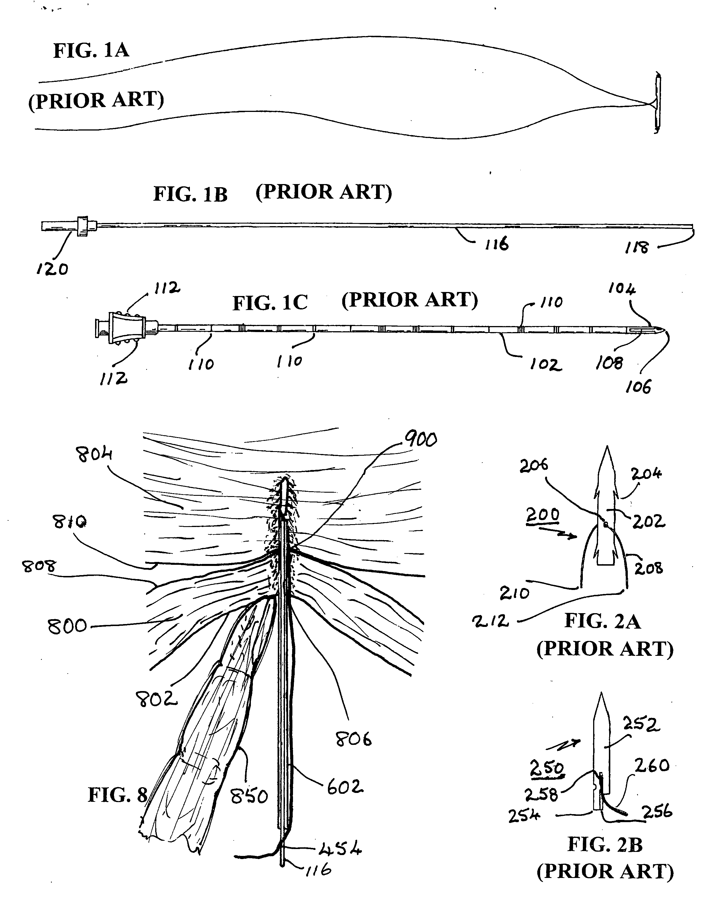
[0038] The third and most important structural element of the combination per the first embodiment is an anchor element 400 (best seen in FIGS. 6 and 7) that is locatable by the previously described body 102 and stylet 116 to support a suture 454 that in turn will support the relocated vagina. LoVuolo teaches an anchor element 150 (best seen in FIG. 1) that is partially tubular and has two similar sutures 152, 152 extending approximately centrally therefrom. This anchor is entirely different from the one employed in the present invention.

[0039] The teaching of LoVuolo, as it relates to these structures, is hereby incorporated herein by reference.

[0040] A detailed description the anchor element 400 per the preferred embodiments is provided below, following a brief discussion of certain features of other known anchors that differ in various key respects.

[0041] Two known anchors 200 and 250, as disclosed in FIGS. 17 and 16 of previously described U.S. Pat. No. 6,334,446 to Beyar, are...

embodiment 600

[0047] As best understood with reference to the partial sectional view of FIG. 6, in a first preferred embodiment 600 of this invention the distal end of elongate needle-shaped body 602 has a sharp bevel-edged distal end 604 with which it can puncture, by movement in the direction of arrow “A”, into and / or through the supporting tissue and the supported tissue. Anchor element 400 has an elongate cylindrical body with a diameter smaller than the internal bore diameter of body 602 within which it is initially held just inboard of sharp-edged end 604. It may optionally, but not necessarily, have a rounded end, preferably with a distal notch or recess 450 sized to receive and hold distal end 452 of a suitable length of suture 454. A knot may be formed at end 452 or some other mechanism employed to retain end 454 in anchor element 400 such that the suture itself extends centrally, e.g., via an axial bore 456, toward the rear of anchor 400.

[0048] Anchor element 400, like anchor element 25...

embodiment 700

[0053] The second preferred embodiment 700 differs from the first one in two significant particulars. First, best understood with reference to FIG. 7, the needle-like body 702 differs from body 602 in that it has an angled sharp-edged distal end ending in a distal point 704. It is provided with a longitudinal slot that is sized so that when anchor element 400 is initially disposed within the slotted region the proximate end 470 of anchor element extends past the proximate end 708 of slot 706. The width of slot 706 must be greater than the base width of the barbs 462, 464 but smaller than the diameter of anchor element 400. This will ensure that at least some of the barbs, 464, extend out of slot 706 beyond the outer surface of body 702 even before any tissue is penetrated; and it will also ensure that anchor element 400 will not be forced sideways out of body 702 by the penetrated tissues as the puncturing process proceeds.

[0054] Most of the barbs 462, if made of preferred stiff but...


PUM


Abstract

In a preferred application, e.g., the repair of vaginal prolapse after relocation of the vagina and any organs displaced by the prolapse, corrective surgery is initiated by applying a hollow tubular element, formed to forcibly insert a barbed anchor attached to a distal end of a first length of suture, without any incision, from the inside of the vagina through the vaginal wall (the supported tissue) into selected support tissue within a patient's pelvis. This involves puncturing and thus locally severe physical distressing of both the supported tissue and the support tissue. The barbed anchor is left in the support tissue as the tubular element is then withdrawn from the support tissue and out of the vagina, leaving the proximate end portion of the suture extending through the vaginal wall into the vagina. A second such anchor, with a second length of suture attached thereto, is similarly inserted adjacent to the first anchor. The proximate end portions of the sutures are tied to each other inside the vagina, to thereby secure the vaginal wall to the support tissue with corresponding punctures formed in each by the insertions of the two anchors being thereby held in respective, precisely aligned, intimate contact during healing. This results in a pair of fused scars that cooperate to permanently bond the vaginal wall locally to the support tissue. If the sutures and / or the anchors are made of absorbable material they will all eventually disappear and the fused scars will provide the permanent bonding. If the anchors are made of non-absorbable material they may remain where located. A plurality of such paired fused-scar bonds may be generated, at the surgeon's discretion, to ensure adequate support for the repaired vagina. The apparatus and method can be readily adapted to similarly effect deliberate, local, beneficial bonding between other adjacent living tissues in a patient.

Description

[0001] This application claims priority to copending U.S. Provisional Patent Application Ser. No. 60 / 553,315 of Mickey M. KARRAM, titled “APPARATUS AND METHOD OF REATTACHING PROLAPSED ORGAN WITH BARB-ANCHORED ABSORBABLE SUTURES”, filed Mar. 15, 2004. FIELD OF THE INVENTION [0002] This invention relates to an apparatus and a method for permanently repairing vaginal prolapse without making incisions. More particularly, the invention relates to an apparatus and a method by which absorbable or nonabsorbable barbed anchors with attached sutures are implanted through an unopened female patient's relocated vagina into selected support tissue without forming any vaginal or abdominal incisions, to generate deliberately fused scarification locally between the vaginal wall tissue and the support tissue for permanent bonding therebetween. BACKGROUND OF THE RELATED ART [0003] Females commonly suffer from pelvic organ prolapse, which results from the breakdown of support structures within the pel...

Claims


Application Information

Patent Timeline
IPC IPC(8): A61B17/04
CPCA61B17/0401A61B17/42A61B2017/4216A61B2017/0437A61B2017/0458A61B2017/0403
Inventor KARRAM, MICKEY M.
Owner KARRAM MICKEY M
Learn More