
Wash fluid containment system

a technology of containment device and wash fluid, which is applied in the direction of cleaning using liquids, vehicle cleaning, sewage draining, etc., can solve the problems of waste water, health hazards and odors, and the containment and disposal of wash fluid, and achieve the effect of rapid deployment and easy leveling

Inactive Publication Date: 2005-09-15
HYDRO ENG EQUIP & SUPPLY
View PDF15 Cites 7 Cited by
  • Summary
  • Abstract
  • Description
  • Claims
  • Application Information

AI Technical Summary

Benefits of technology

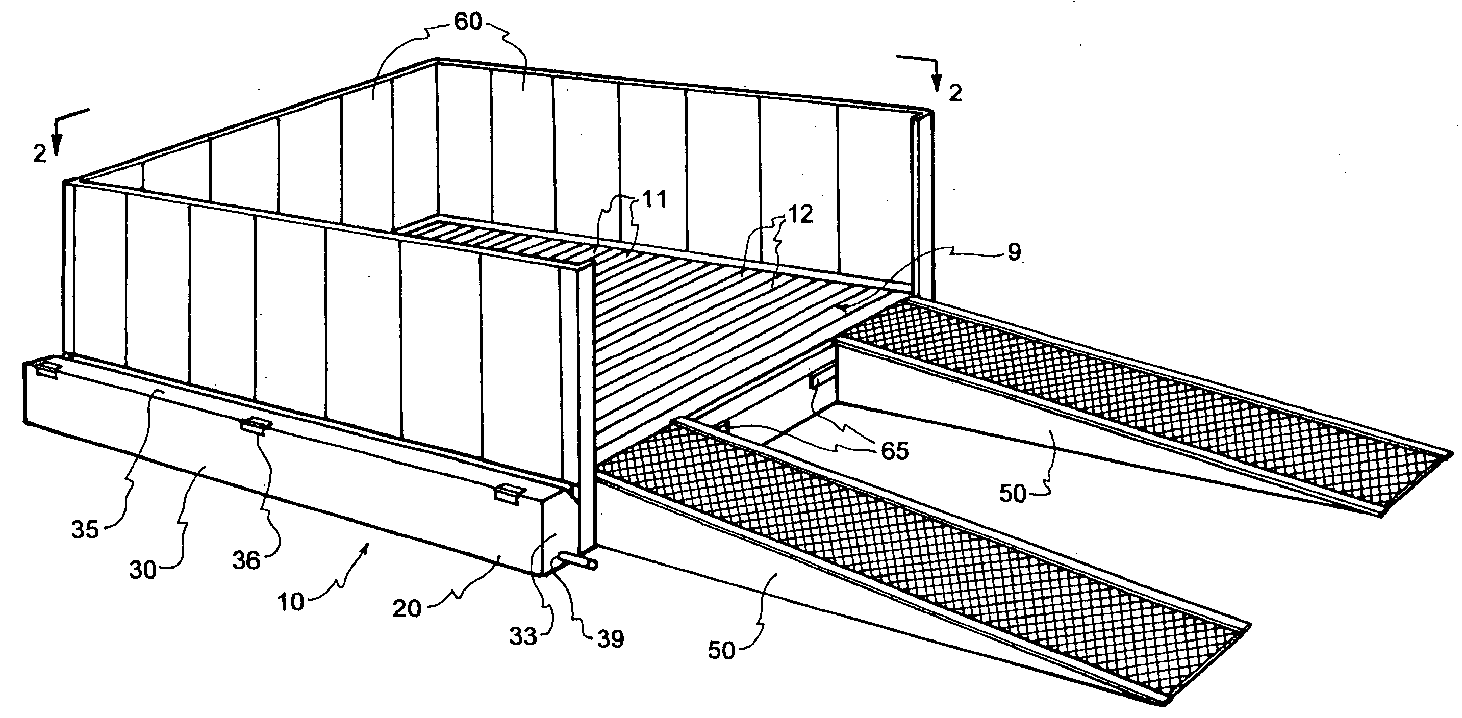
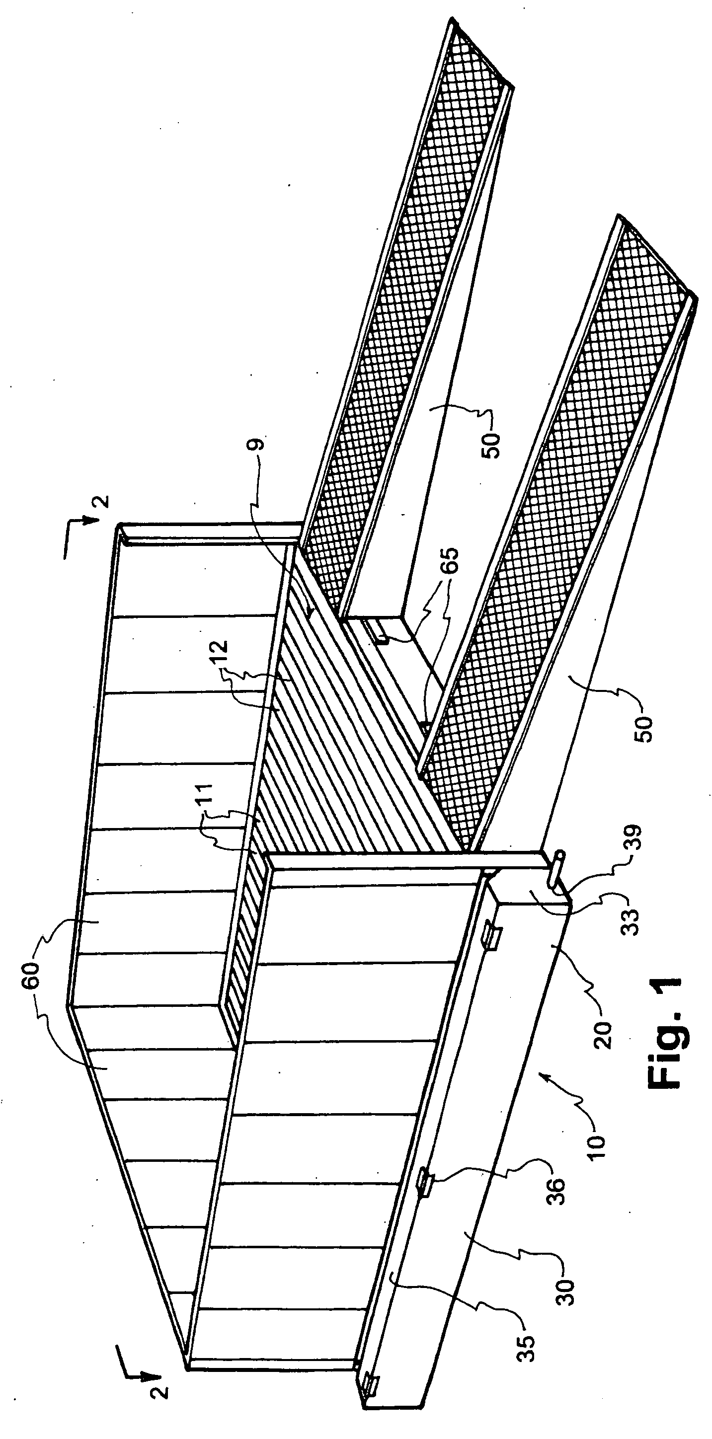
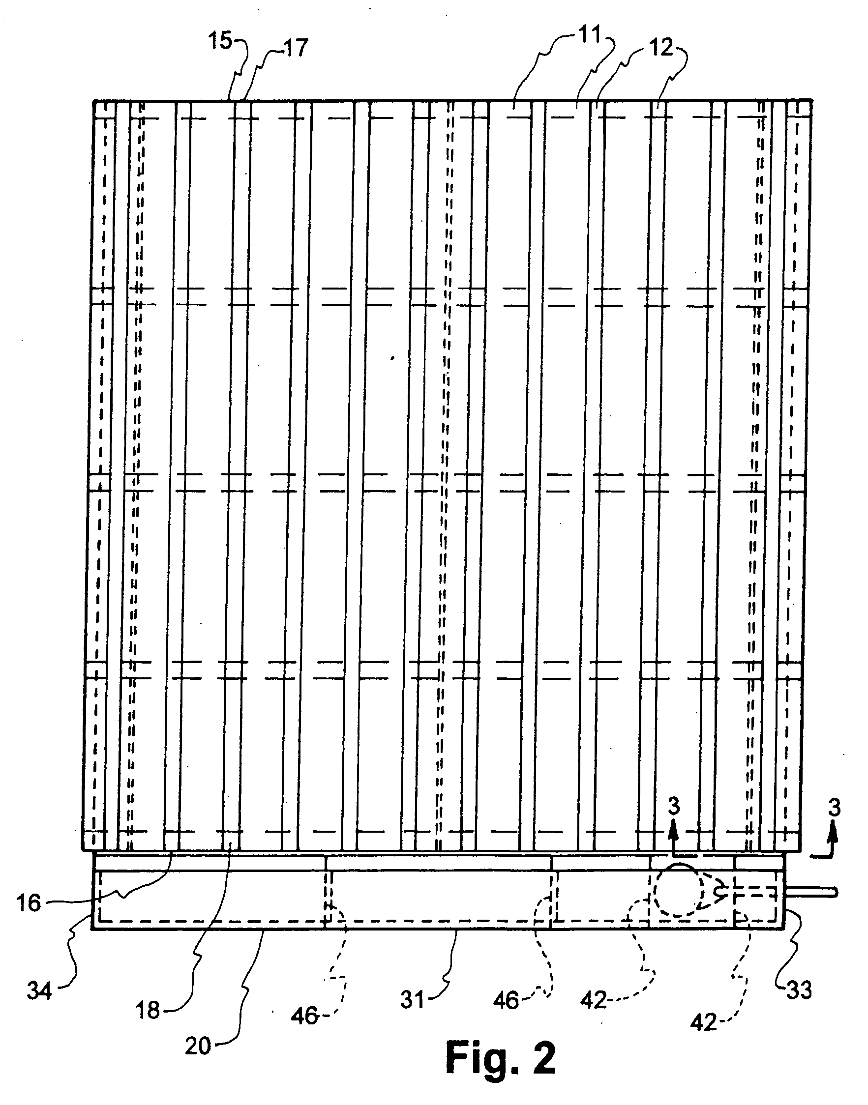
[0010] In a presently preferred embodiment of the elevated surface, the surface is formed to have a plurality of supporting rails which support a vehicle or other piece of equipment thereon and a plurality of fluid flow channels located between the rails so that wash fluid, solids, and debris from the vehicle or other item being washed flow into the channels. The channels are open at one end along one side of the device and may be sloped toward the open end so that the wash fluid will flow through the channels and out the open ends of the channels into the collecting trough positioned along the side of the device in flow communication with the plurality of channels. Since the collecting trough is located along the side of the device it is easily accessible for cleaning and solids removal during use of the device. The flow channels can be easily cleaned without disassembly (such as removal of a covering grate) of the device and such cleaning can take place during use of the device or as part of the use of the device. No disassembly of the device is necessary for cleaning or solids and debris removal.
[0011] The device preferably is constructed in modules which are portable and can be used singly for small vehicles and other equipment or can be combined with additional modules to create a larger device to accommodate large trucks and other large equipment. Modules of eight feet by eight, ten, twelve, or fourteen feet have been found satisfactory, although other sizes can be used. Such modules can be secured side-by-side or end-to-end to create larger washing surfaces. Walls and, if desired, a roof can be attached to the collecting devices to partially or fully enclose them to help ensure that all wash fluid stays on the device rather than being sprayed or splashed off the device. When enclosed, lighting and ventilation can also be provided.
[0012] Portable devices of the invention are preferably structurally rigid and provided with fork lift slots and lift points that allow rapid deployment on unimproved dirt surfaces. Such portable devices can be easily leveled as with shims and be ready to use generally in less than a day. Because they are portable, most localities consider them to be personal property which eliminates any permitting and inspection requirements which would be present if permanent washing facilities were being constructed.

Problems solved by technology

With increased concern for the environment, washing items, particularly large items such as vehicles, can raise a problem of containment and disposal of wash fluid, usually water.
With open holding tanks, wastewater builds up with inevitable formation of bacteria which create health hazards and odor.
Also, such permanent sites now may require special permitting since they contain what may be considered as hazardous materials.
A further problem is that during washing of an item it may be difficult for an operator to keep the fluid jet used for washing from impacting the fluid in the basin.
This not only requires that the object to be cleaned again, but it also creates operator hazards because of the chemical and biological agents contained in the basin.
Such cleaning is difficult, time consuming, and renders the washing pad unusable during such cleaning.
This is difficult and time consuming and renders the washing pad unusable during the cleaning process.
Another problem with portable systems is that the collecting tanks are relatively shallow.
With relatively shallow tanks, a slight variation in elevation, such as when placed on an uneven surface, can cause one end of the tank to be dry while another overflows, defeating the purpose of using the tank.
If the deep end does not contain a suitable drain, it is virtually impossible to remove fluid from the tank.
Further, the capacity of the tank is seriously reduced in such situations which then requires more frequent cleanings.

Method used


Image

  • Wash fluid containment system
  • Wash fluid containment system
  • Wash fluid containment system

Examples


Embodiment Construction

[0023] In a preferred embodiment, the invention takes the form of a structurally rigid, portable device, generally referred to as a washing pad. The device provides an elevated, substantially water impervious surface upon which items to be washed are positioned. Any wash fluid, generally water, sometimes with added soap, detergent, and / or wax, used to wash the item, will flow from the item onto the surface and be directed to a side of the surface. Contaminants, solids, and debris washed from the item will generally flow with the wash fluid to a side of the surface, or may be washed from the surface with additional wash fluid. The wash fluid, with any contaminants, solids, and debris threrin, is collected in a receiving and collecting trough as it flows from the side of the surface. The pad is placed on the ground (unimproved or improved dirt surface, asphalt, concrete or other surface) and is elevated above ground level so that the collecting trough is positioned between the surface...


PUM

PropertyMeasurementUnit
Lengthaaaaaaaaaa
Pressureaaaaaaaaaa
Sizeaaaaaaaaaa

Abstract

A wash fluid containment system includes an elevated, fluid impervious surface upon which items to be washed are placed for washing. The surface is configured to cause wash fluid to flow to an edge of the surface and off of the surface to prevent buildup of wash fluid on the surface. A collecting trough is positioned in fluid flow communication with the edges of the surface to which the fluid flows to catch and collect the fluid as it flows from the surface. Used wash fluid is taken from the collecting trough for disposal or recycling and solids and debris can be easily removed from the trough.

Description

BACKGROUND OF THE INVENTION [0001] 1. Field [0002] The invention is in the field of containment devices and systems for wash fluid, generally wash water, used in washing objects such as vehicles and equipment where the wash water after washing may have contaminants or a high solids content such as when washing dirt, oils, and mud from a vehicle. [0003] 2. State of the Art [0004] With increased concern for the environment, washing items, particularly large items such as vehicles, can raise a problem of containment and disposal of wash fluid, usually water. The wash fluid can contain various contaminants ranging from soap, detergent, and wax which may be added to the fluid prior to washing; gasoline, oil, and grease that may be washed from a vehicle or other piece of equipment; to various other contaminants and solids that build up on a vehicle or other equipment during use and are washed off with the wash fluid. [0005] Permanent wash sites have washing pads which collect the used was...

Claims


Application Information

Patent Timeline
IPC IPC(8): B08B17/00B60S3/00E03F1/00F16N31/00
CPCB08B17/00B08B17/025F16N31/006B60S3/04E03F1/00B60S3/00
Inventor MCCORMICK, JAMES P.MCCORMICK, ALAN G.SMITH, KERRY G.
Owner HYDRO ENG EQUIP & SUPPLY
Learn More