Vehicle brake device

a brake device and vehicle technology, applied in the direction of automatic initiation, brake system, transportation and packaging, etc., can solve the problems of inability to rely on, excessive load may be applied to the driver's foot, and the driver cannot achieve the effect of braking

Inactive Publication Date: 2005-09-15
ADVICS CO LTD
View PDF10 Cites 24 Cited by
  • Summary
  • Abstract
  • Description
  • Claims
  • Application Information

AI Technical Summary

Benefits of technology

[0013] Accordingly, it is a primary object of the present invention to provide an improved vehicle brake device which is capable of reliably detecting a time point when a brake pedal begins to be pushed up upon collision of the vehicle and of withdrawing

Problems solved by technology

This may results in pushing up a brake pedal in a rearward direction, i.e., toward the driver, whereby an excessive load may be applied onto the driver's foot.
Thus, it may occur that during the

Method used


Image

  • Vehicle brake device
  • Vehicle brake device
  • Vehicle brake device

Examples


first embodiment

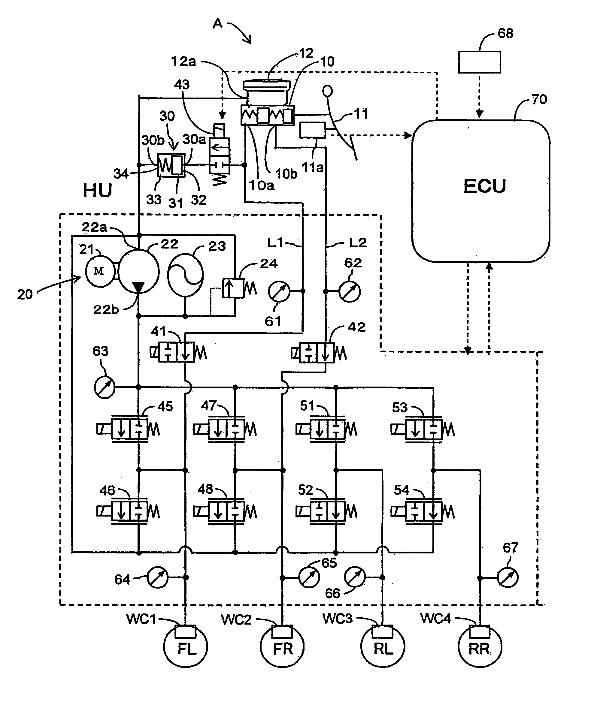
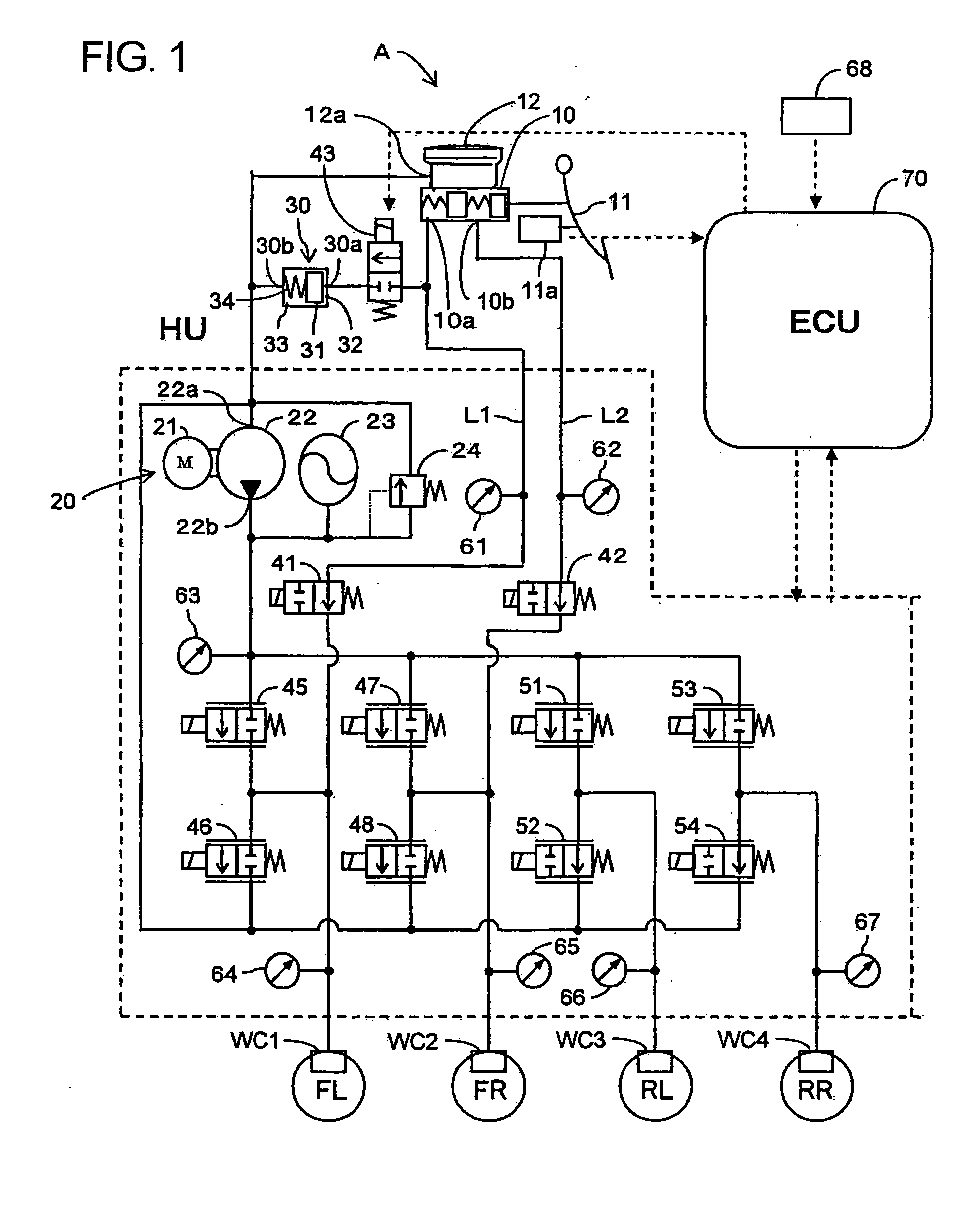
[0029] A vehicle brake device in a first embodiment according to the present invention will be described hereinafter with reference to the accompanying drawings. As shown in FIG. 1, a vehicle brake device A in this embodiment is of a so-called “brake-by-wire type” and in particular, is of the type having a mechanical stroke simulator. The device A is provided with a master cylinder 10 for generating the fluid pressure which depends on the stepping state of a brake pedal 11, and a pressurized fluid supply source 20 provided independently of the master cylinder 10 for supplying pressurized fluid to wheel cylinders WC1, WC2, WC3 and WC4 which respectively restrict rotations of left and right front wheels FL, FR and left and right rear wheels RL, RR of a vehicle (not shown). The brake device A is constructed so that in the normal (i.e., properly operating) state of the pressurized fluid supply source 20, the pressurized fluid whose pressure depends upon the brake pedal stepping force is...

second embodiment

[0082] Hereinafter, a vehicle brake device in a second embodiment according to the present invention will be described with reference to FIG. 8. FIG. 8 is a fluid circuit diagram showing the schematic construction of the vehicle brake device A in this embodiment. The components in the second embodiment which are identical to those in the first embodiment are given the same reference numerals as used in the first embodiment and are omitted from being described in detail. Therefore, the following description is addressed to the respects which are different from those in the first embodiment.

[0083] Although in the foregoing first embodiment, description has been made taking examples wherein the present invention is applied to the hydraulic type vehicle brake device of so-called “brake-by-wire type” and in particular, to that of the type having a mechanical stroke simulator, the present invention may be applied to a vehicle brake device of the type that a stroke simulator used therein ...

third embodiment

[0087] Hereinafter, a vehicle brake device in a third embodiment according to the present invention will be described with reference to FIG. 9. FIG. 9 is a fluid circuit diagram showing the schematic construction of the vehicle brake device A in this embodiment. The components in the third embodiment which are identical to those in the first embodiment are given the same reference numerals as used in the first embodiment and are omitted from being described in detail. Therefore, the following description is addressed to the respects which are different from those in the first embodiment.

[0088] The vehicle brake device A is of the type which is included in hydraulic vehicle brake device and has functions for securing the vehicle stability during acceleration and turn (e.g., VSC (Vehicle Stability Control) and TRC (Traction Control)). The vehicle brake device A is provided with a master cylinder 210 which generates brake oil of the fluid pressure corresponding to the stepping state o...


PUM


Abstract

A vehicle brake device A is provided with a master cylinder 10, a reservoir tank 12, solenoid valves 46 and 48 for adjustably draining brake oil from outlet ports 10a, 10b of the master cylinder 10 to the reservoir tank 12, a collision detection sensor 68 for detecting a collision of the vehicle, a fluid pressure meter 61 for detecting the master cylinder pressure, and an ECU 70. The ECU 70 detects the pushing-up of the brake pedal 11 based on the occurrence of a collision and the master cylinder pressure, and upon detection of the pushing-up, controls the solenoid valves 46 and 48 to adjust the draining of the brake oil so that the brake pedal 11 is withdrawn. Thus, a time point when the brake pedal 11 begins to be pushed up by the cause of the vehicle collision can be detected accurately and reliably, and the brake pedal 11 can be withdrawn accurately in dependence on the pushing-up. This reliably secures an anchorage upon which the driver keeps his body balance and reliably prevents an excess load from being exerted on the driver.

Description

[0001] This application claims priority under 35 U.S.C. 119 with respect to Japanese Applications No. 2004-068134 and No. 2005-001567 respectively filed on Mar. 10, 2004 and Jan. 6, 2005. BACKGROUND OF THE INVENTION [0002] 1. Field of the Invention [0003] The present invention relates to a vehicle brake device for braking a vehicle by the stepping manipulation of a brake pedal. [0004] 2. Discussion of the Related Art [0005] Heretofore, in vehicle brake devices of this kind, where an impact of more than a predetermined magnitude is exerted on a vehicle at the time of a crash, collision or the like, the rearward displacements of an engine and the like cause a master cylinder to be displaced rearward. This may results in pushing up a brake pedal in a rearward direction, i.e., toward the driver, whereby an excessive load may be applied onto the driver's foot. To cope with this, there have been known those in which upon detection of a collision, brake oil in a master cylinder is forced t...

Claims


Application Information

Patent Timeline
IPC IPC(8): B60T8/00B60T7/06B60T8/42B60T17/18
CPCB60T7/065B60T7/22B60T8/32B60T8/3255B60T8/4072B60T13/686B60T8/409B60T8/4275B60T8/4872B60T13/662B60T8/4081
Inventor KAMIYA, MASAHIKOSEGAWA, TAROMATSUHASHI, TAKAAKI
Owner ADVICS CO LTD
Why Eureka
Try Eureka