
Switching regulator and control method therefor

a switching regulator and control method technology, applied in the direction of automatic control, process and machine control, instruments, etc., can solve the problems of increasing noise level, and achieve the effect of reducing noise level, reducing noise level, and increasing noise level

Inactive Publication Date: 2005-09-15
DENSO CORP
View PDF10 Cites 20 Cited by
  • Summary
  • Abstract
  • Description
  • Claims
  • Application Information

AI Technical Summary

Benefits of technology

[0007] It is therefore an object of the present invention to reduce a noise level of a frequency modulation type switching regulator.
[0008] According to the present invention, in a frequency modulation type switching regulator for producing an output voltage to a load, an error voltage indicative of a difference between the output voltage and a reference voltage is produced and a switching device is turned on and off at a switching frequency corresponding to the error voltage. An operation condition of the load is monitored. The operation condition may be detected by using the error voltage. A varying voltage, which varies around the error voltage, is generated when the monitored operation condition is substantially unchanged. The switching frequency is switched to another frequency corresponding to the varying voltage, so that noise level may be reduced.
[0009] In the frequency modulation type switching regulator, the output current and hence the output voltage changes when the operation condition of the load changes. The switching frequency therefore changes to regulate the output voltage to a target reference voltage. The switching frequency also becomes substantially unchanged, when the operation condition of the load become substantially unchanged. As a result, the noise harmonic component energy concentrates and the noise level increases. By varying the switching frequency in this condition, the noise harmonic component energy is distributed to lower the noise level.

Problems solved by technology

As a result, the noise harmonic component energy concentrates and the noise level increases.

Method used


Image

  • Switching regulator and control method therefor
  • Switching regulator and control method therefor
  • Switching regulator and control method therefor

Examples


Embodiment Construction

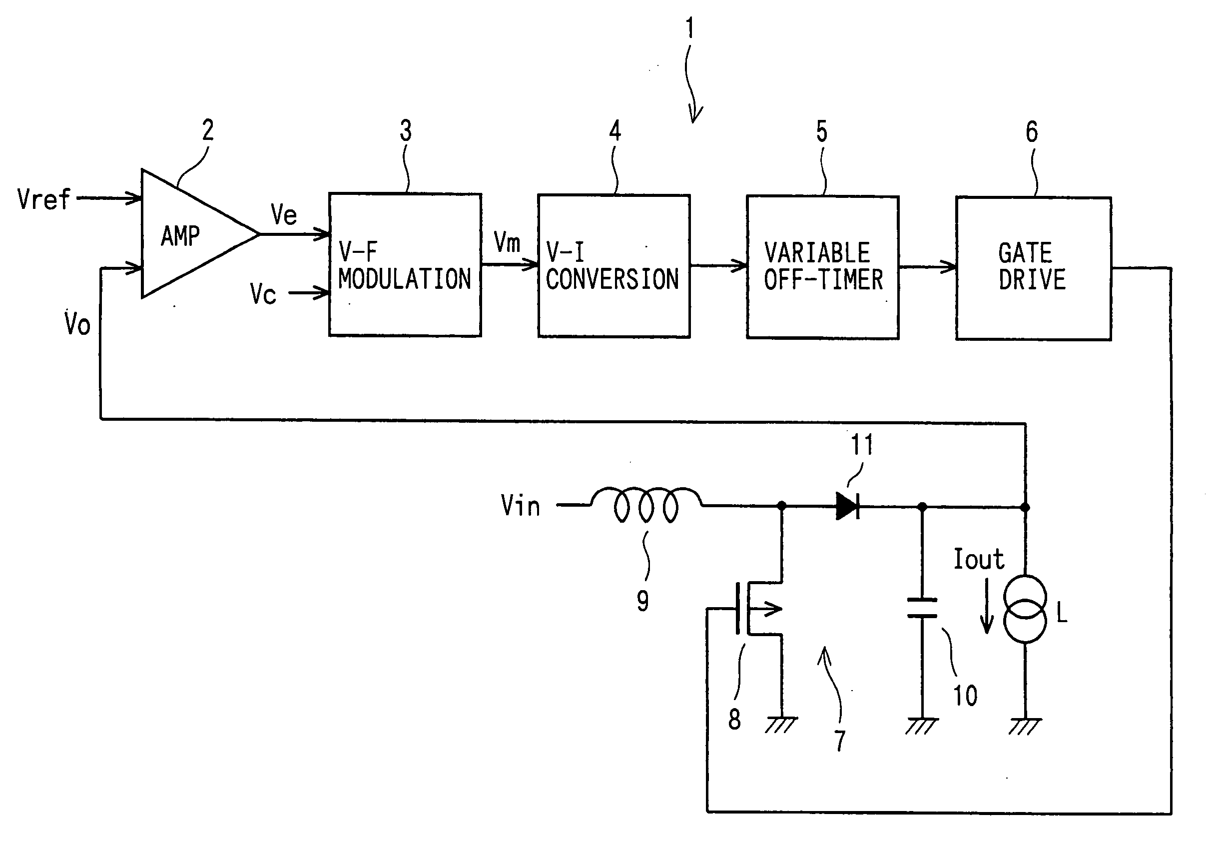
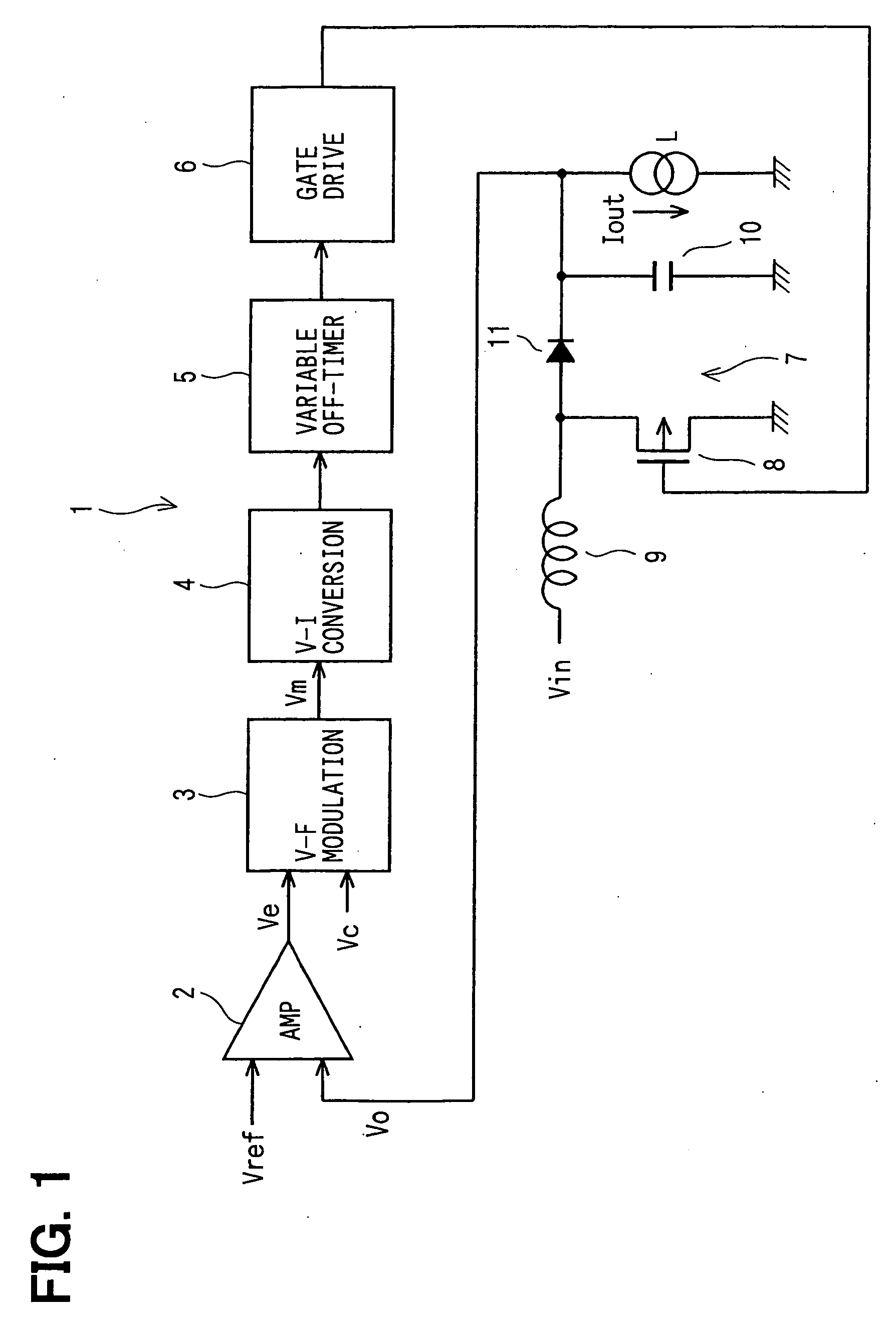
[0014] Referring to FIG. 1, a frequency modulation type switching regulator 1 includes an error amplifier 2, a voltage-frequency (V-F) modulation circuit 3, a voltage-current (V-I) conversion circuit 4, a variable off-timer 5, a gate drive circuit 6 and a switching circuit 7. The above construction other than the voltage-frequency modulation circuit 3 is conventional.

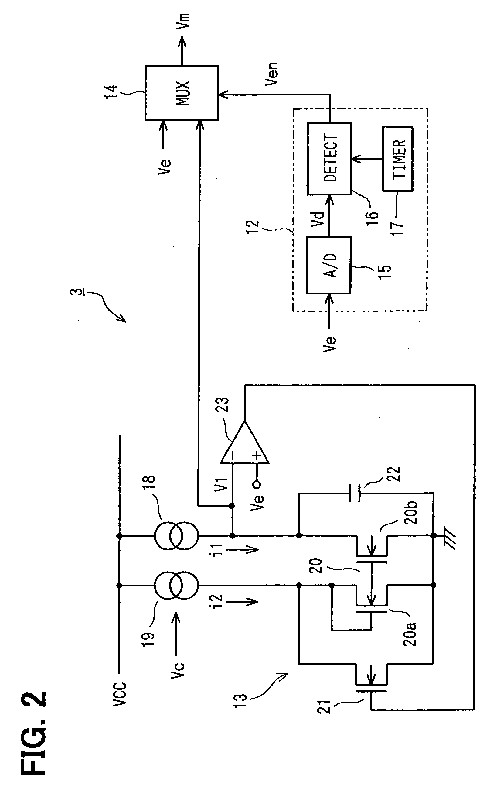
[0015] The error amplifier 2 outputs an error voltage Ve, which is a difference between a reference voltage Vref and an output voltage Vo, to the voltage-frequency modulation circuit 3. The modulation circuit 3 monitors the error voltage Ve, and outputs as a voltage Vm either the error voltage Ve or a varying voltage V1.

[0016] The conversion circuit 4 converts the voltage Vm to a current. The off-timer 5 variably sets its off-time of switching in accordance with the current or the voltage Vm. The drive circuit 6 drives, based on on-off timing pulses set by the off-timer 5, the gate of a P-channel MOSFET 8 used as a sw...


PUM


Abstract

In a frequency modulation type switching regulator for producing an output voltage to a load, an error amplifier produces an error voltage indicative of a difference between the output voltage and a reference voltage. A switching device is turned on and off at a switching frequency corresponding to the error voltage. A voltage-frequency modulation circuit monitors an operation condition of the load. The modulation circuit generates a varying voltage, which varies around the error voltage, when the monitored operation condition is substantially unchanged. The switching frequency is switched to another frequency corresponding to the varying voltage, so that noise level may be reduced.

Description

CROSS REFERENCE TO RELATED APPLICATION [0001] This application is based on and incorporates herein by reference Japanese Patent Application No. 2004-65550 filed on Mar. 9, 2004. FIELD OF THE INVENTION [0002] The present invention relates to a frequency modulation type switching regulator, which generates a regulated output voltage by varying the switching frequency of a switching device, and a control method for the same. BACKGROUND OF THE INVENTION [0003] A switching regulator is constructed to generate a regulated output voltage by repetition of a switching operation of a switching device, and therefore the switching device generates unnecessary radiation noises at the time of switching operation. The regulated output voltage does not vary so much in the stationary condition in which the operating condition of a load to which the regulated output voltage is applied from the switching regulator is substantially unchanged. [0004] As a result, the switching device performs switching ...

Claims


Application Information

Patent Timeline
Patent Type & Authority Applications(United States)
IPC IPC(8): G05F1/40H02M3/155
CPCH02M3/156H02M1/44
Inventor UEDA, GORO
Owner DENSO CORP
Learn More