Anisotropic conductive sheet

Inactive Publication Date: 2005-09-15
JST MFG CO LTD
View PDF16 Cites 4 Cited by
  • Summary
  • Abstract
  • Description
  • Claims
  • Application Information

AI Technical Summary

Benefits of technology

[0008] Therefore, a conductive elastomer having characteristics suitable for anisotropic conductive sheets is combined with a material characterized by having relatively low dielectric constant and / or dielectric loss, whereby it is made possible to reliably transmit signals between a board and a component or between boards in addition to preventing the attenuation of RF signals or signals including RF waves. For example, an anisotropic conductive sheet having desired characteristics can be provided by forming an insulative matrix member of the anisotropic conductive sheet from a resin material having a resin foamed body of a foaming structure, i.e. one of homogeneous microcell structures, and arranging at least one conductive member as an element so as to be inserted in the matrix member like a cell penetrating from the top to bottom surface of the anisotropic conductive sheet.
[0019]“The conductive and matrix members are bonded chemically” may include that the conductive and matrix members are bonded by an adhesive agent, etc. The conductive and matrix members may be bonded at the entire area of their interfaces, or may be partially bonded at the their interfaces. In a case where the members are bonded chemically in this way, it becomes possible to effectively prevent the interfaces from being dislocated owing to compressive strains, etc. In addition, when a compressive force is removed, the sheet can be restored from such strained condition effectively.

Problems solved by technology

It is not necessarily easy to correctly measure the degree of attenuation of RF signals for each component.

Method used


Image

  • Anisotropic conductive sheet
  • Anisotropic conductive sheet
  • Anisotropic conductive sheet

Examples


examples

[0060] The embodiment of the present invention will be described below in reference to the drawings. However, in the description on the embodiment, specific materials, numerical values, etc. are cited merely as preferred examples according to the present invention and as such, the present invention is not limited to the embodiment.

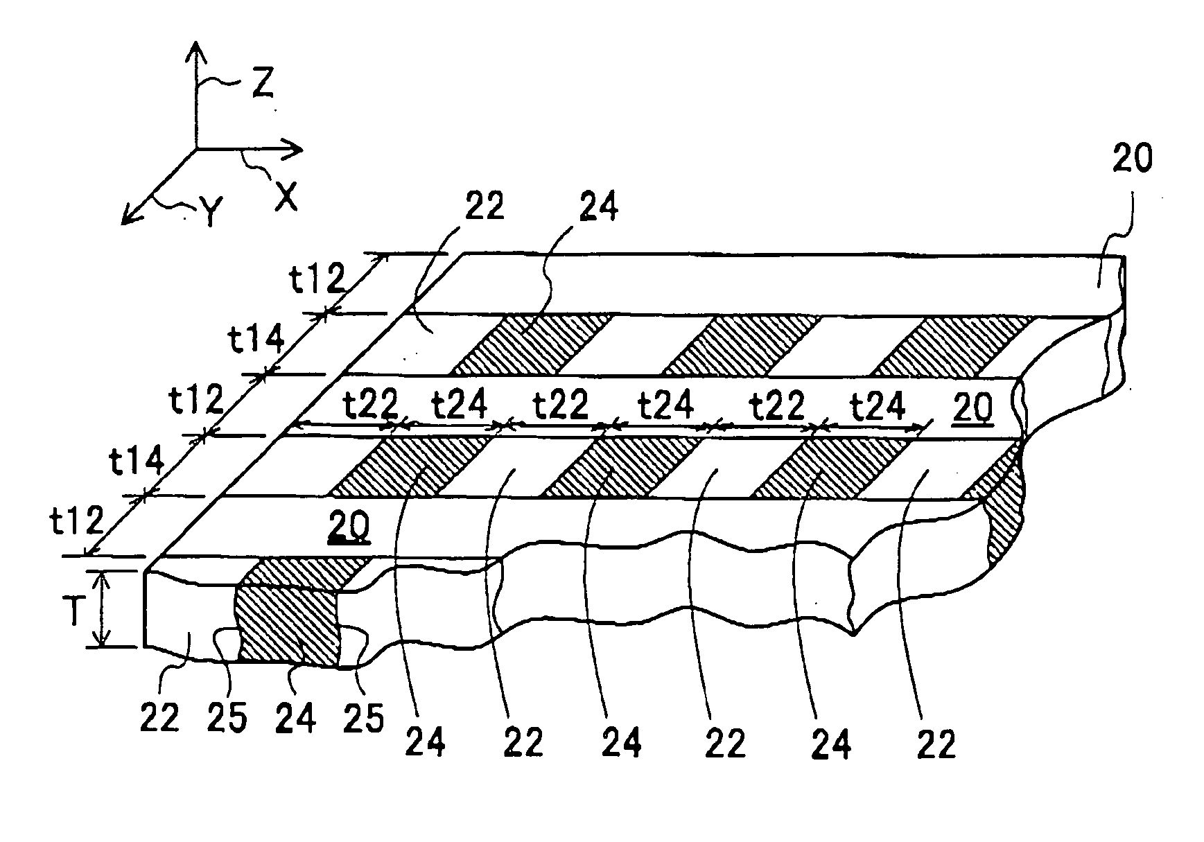
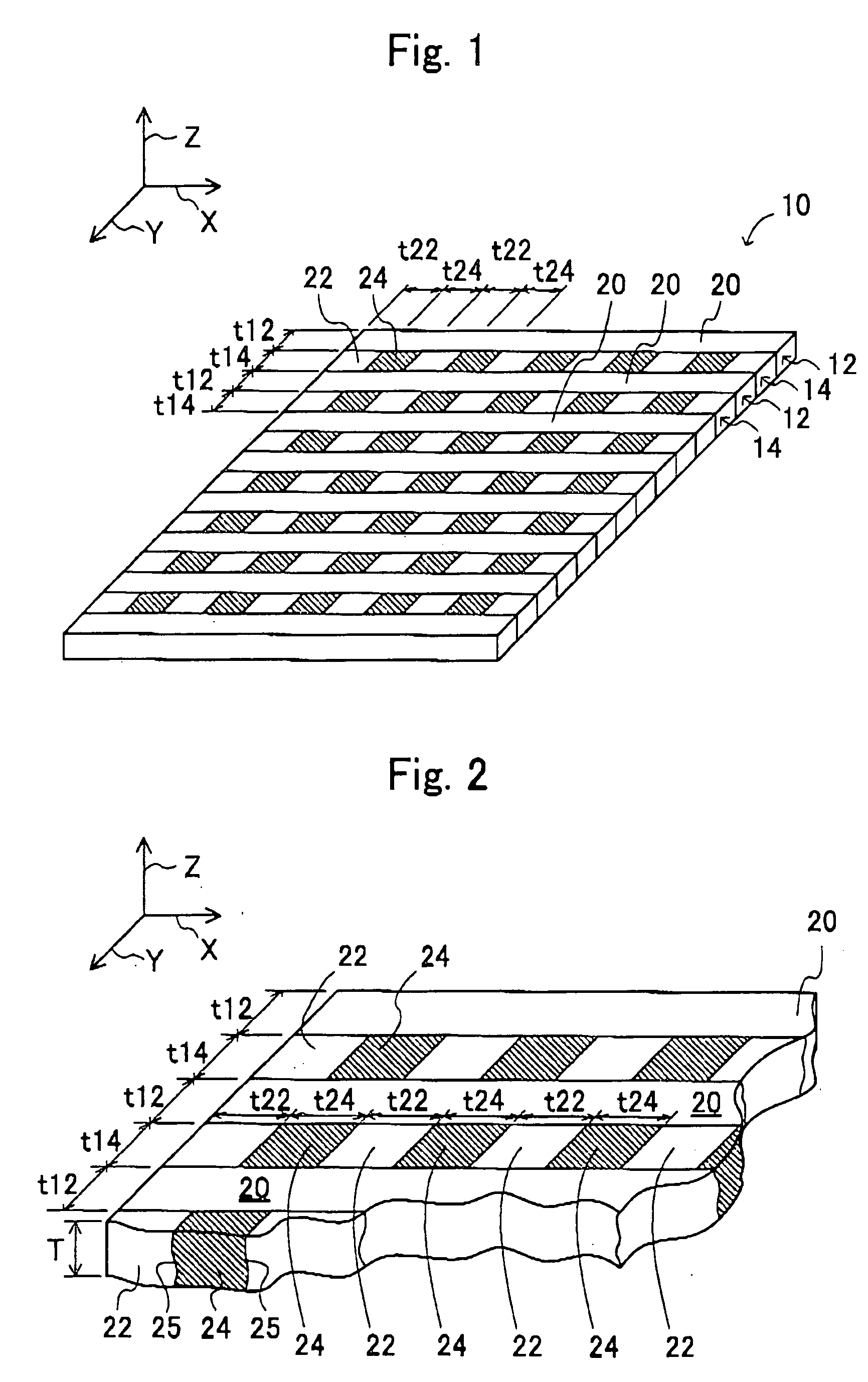
[0061]FIG. 1 shows an anisotropic conductive sheet 10 as an embodiment of the present invention. The anisotropic conductive sheet 10 of the embodiment is a rectangular sheet member and is configured by alternately disposing: belt-shaped members 12 each composed of a non-conductive member; and striped, belt-shaped members 14 each having conductive members and non-conductive member alternately disposed. The adjacent belt-shaped member 12 composed of the non-conductive member and striped, belt-shaped member 14 are bonded by a coupling agent. For the anisotropic conductive sheet of the embodiment, a conductive silicone rubber manufactured by Shin-Etsu Polymer...


PUM


Abstract

An anisotropic conductive sheet capable of transmitting high-speed digital signals reliably is provided. The anisotropic conductive sheet has a conductive property in a thickness direction thereof under a predetermined condition, and includes: insulative matrix members having a dielectric constant value of at most 2.28 and a dielectric loss value of at most 0.025; and conductive members having a conductive property in the thickness direction under the predetermined condition in the conductive members capable of flowing electricity between top and bottom surfaces thereof are located in a scattered manner in the matrix members, and the conductive and matrix members are bonded chemically. Especially, the matrix member is made from a resin material having a resin foamed body of a foaming structure, i.e. homogeneous microcell structure. At least one of the conductive members may be of conductive elastomer.

Description

CROSS-REFERENCE TO RELATED APPLICATIONS [0001] This application is based upon and claims the benefits of priority from Japanese Patent Application No. 2004-068176 filed on Mar. 10, 2004, the entire contents of which are incorporated herein by reference. FIELD OF THE INVENTION [0002] The present invention relates to an anisotropic conductive sheet, and more specifically an anisotropic conductive sheet capable of transmitting radio frequency (RF) signals or high-speed digital signals. RELATED ART [0003] In recent years, the number of devices handling digital signals, namely potential RF signals substantially, such as computers and cellular telephones have been increasing with the progress of information and communication technology. Therefore, with printed wiring boards used for those devices, there have been coveted the ones which are superior in RF characteristics and low in both dielectric constant and dielectric loss. In general, an epoxy resin laminated sheet with a glass base, a...

Claims


Application Information

Patent Timeline
IPC IPC(8): B61D15/08H01H73/00H01L21/3205H01L21/4763H01R12/00H01R13/24H01R13/44H01R13/62H01R13/66H02H3/00H02H7/00H02H9/02H05K1/00H01R11/01H05K1/02H05K3/36
CPCH01R13/2414H01R23/688H01R43/007H05K2203/0235H05K2201/0314H05K2201/10378H05K3/368
Inventor HASEGAWA, MIKI
Owner JST MFG CO LTD
Why Eureka
Try Eureka