
Combination service entrance apparatus for temporary and permanent use

a service entrance and combination technology, applied in the field of electric power distribution devices, can solve the problems of increasing the cost of building and ultimately the consumer, increasing the cost of building and building materials, and existing combination service entrance devices, as assembled by their manufacturers, when installed, and not meeting the accessibility restrictions of the national electrical code (nec). to achieve the effect of reducing costs and tim

Inactive Publication Date: 2005-09-15
BACA WILLIAM C
View PDF19 Cites 7 Cited by
  • Summary
  • Abstract
  • Description
  • Claims
  • Application Information

AI Technical Summary

Benefits of technology

[0012] A primary advantage of the present invention is that the present invention can be converted form a temporary installation to a permanent installation with minimal modification.

Problems solved by technology

This setting of temporary power service results in the undesirable added expense, scheduling time to both the utility company and the builder.
In addition, the design of the system must meet codes and standards set by local governments, and utilities that are usually more restrictive than the national minimum standard.
The current art in this area does not meet market requirements, where the codes and the standards of the utility company are restrictive, resulting in higher costs to the builder and ultimately the consumer.
Many local governments allow individuals or end users to perform “craft” installations or modifications for combination service entrance devices due to the lack of these units in the marketplace.
These “craft” installations may and usually do not meet the several code requirements by the various enforcement authorities.
Existing combination service entrance devices, as assembled by their manufacturers, when installed, do not meet accessibility restrictions of the National Electrical Code (NEC), and utility companies.
Secondly, a critical requirement is not met by the Leach, et al., patent.
With the unitary design of the enclosure for both the utility side enclosure and the customer side, these specifications cannot be met.

Method used


Image

  • Combination service entrance apparatus for temporary and permanent use
  • Combination service entrance apparatus for temporary and permanent use
  • Combination service entrance apparatus for temporary and permanent use

Examples


Embodiment Construction

)

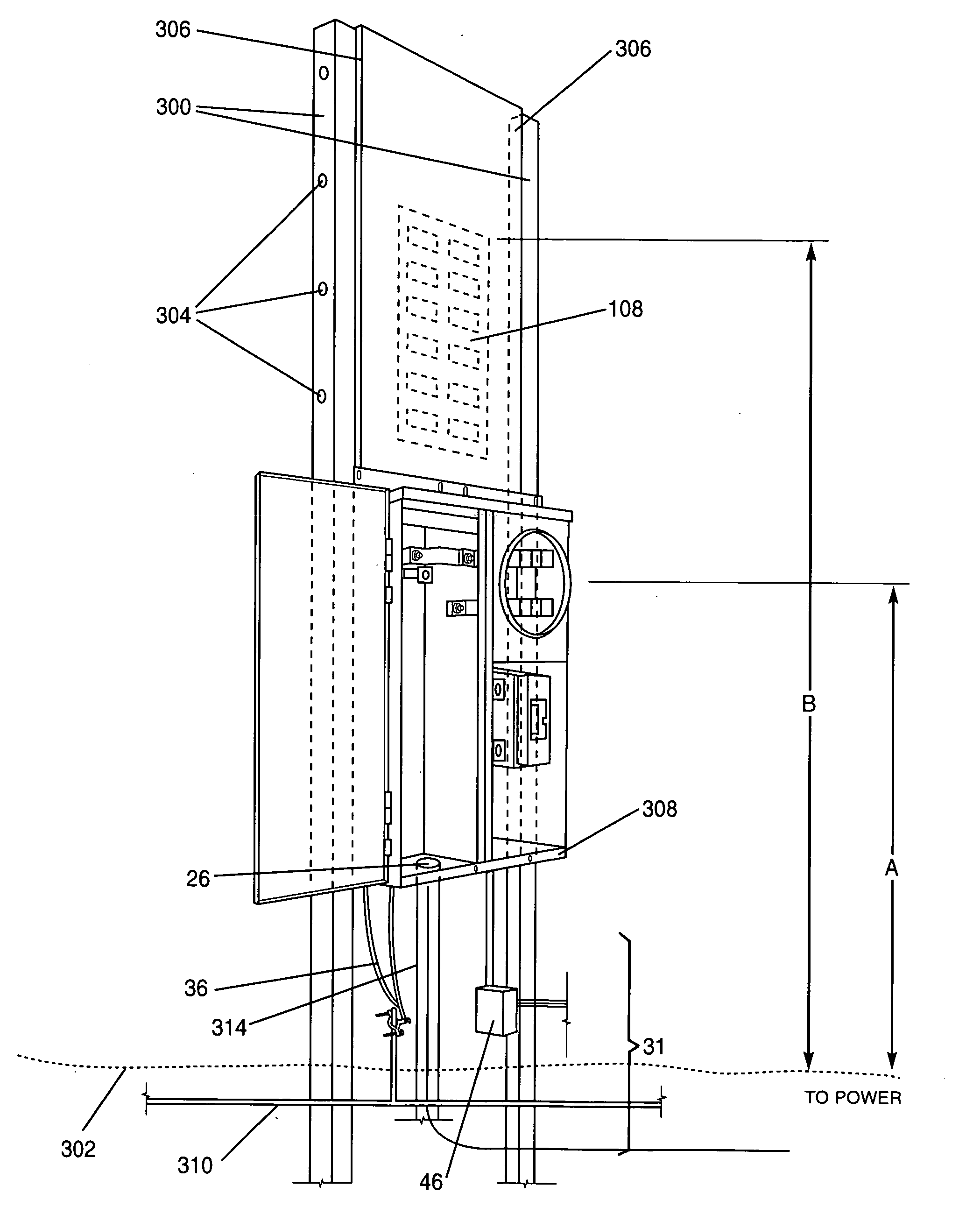
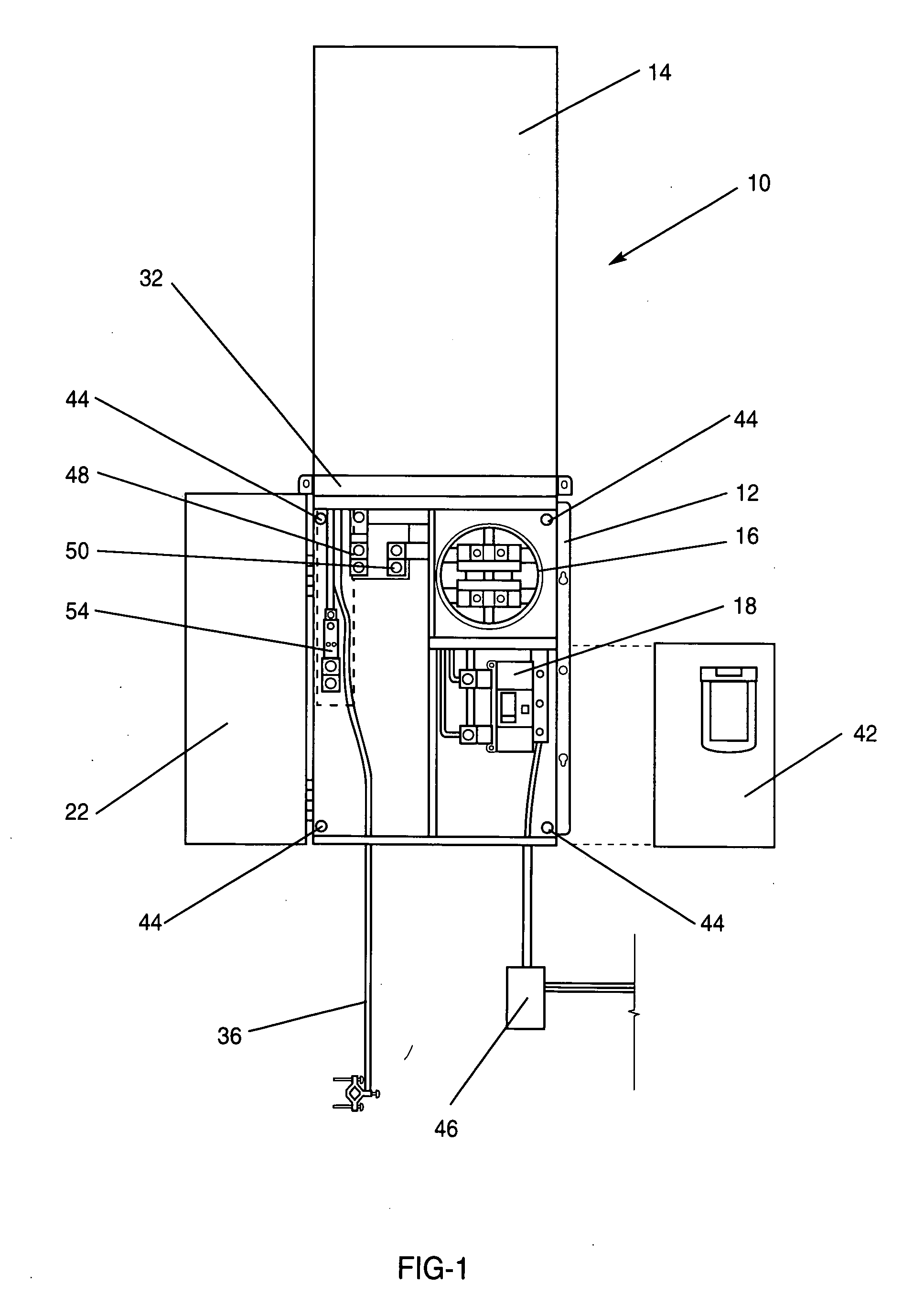
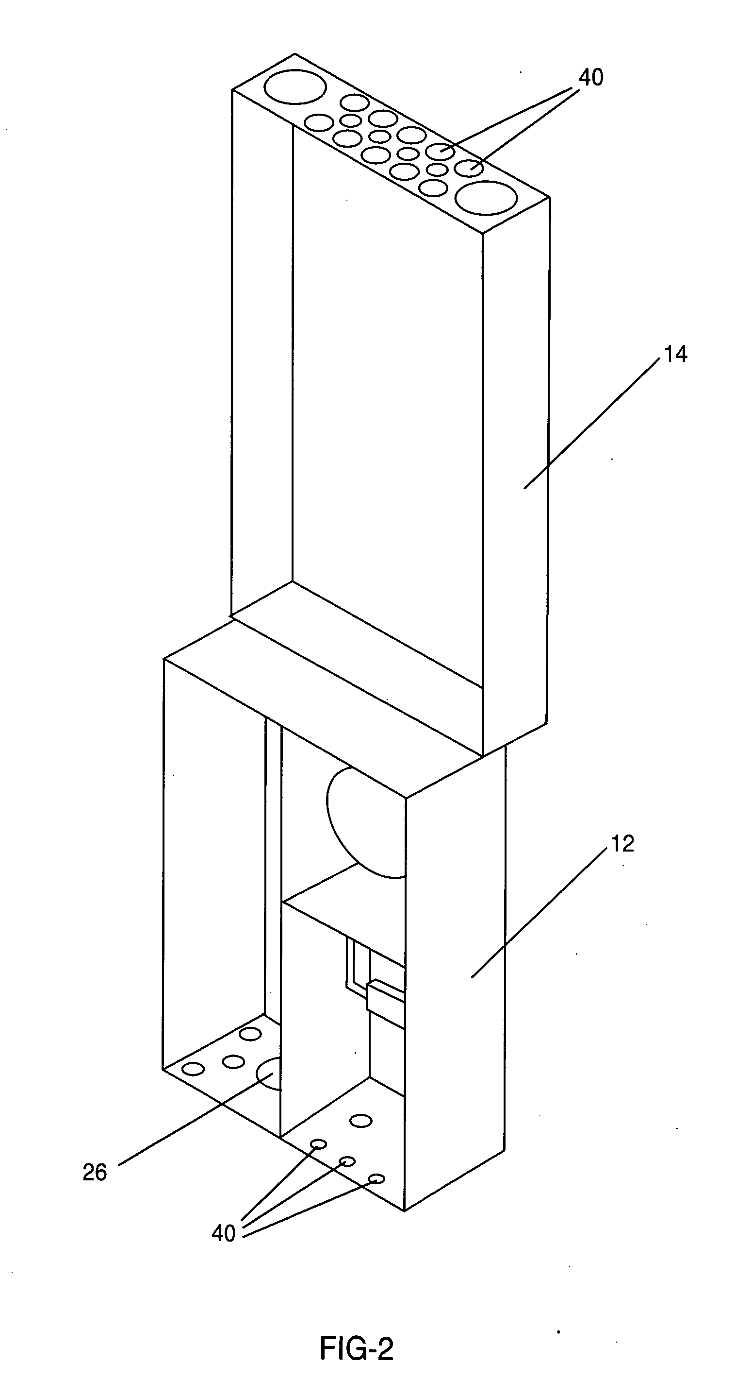
[0023] The presently invented combination service was designed for a temporary and permanent service for new construction. Using the prior art temporary service connections, several builders have been fined by OSHA or other regulatory agencies for unsafe practices for the use of their temporary pole service. They were missing wires, bare wires, were missing covers and the like. To obviate the problem, the applicant designed a panel that would be a temporary / permanent service type application and meet the regulatory agency's requirements. There are no available factory made service entrances that meet the State or NEC codes, thus the need for the present invention. Additionally, the prior art combination services were not adaptable to be reconfigured to meet the differing utility company requirements for meter height and the standard NEC height for the circuit breakers.

[0024] The preferred embodiment of the present invention showing the uncovered utility enclosure 12 is shown in FI...


PUM


Abstract

An underground combination service entrance apparatus for temporary and permanent service comprising two enclosures. A utility enclosure contains a meter socket and the second enclosure contains a breaker panel. The breaker panel on the customer side and the meter on the utility side meet NEC requirements and the local utility company regulations. An optional section in the utility enclosure provides a raceway space for routing wiring. Knockout holes are provided on the utility enclosure for installation of a hub for running wires to and from the service apparatus. The enclosures can be semi-flushed mounted. The two enclosures are isolated from each other, fastened together, and mounted on a wall. A removable hood is provided to weatherproof the customer enclosure for temporary use.

Description

CROSS-REFERENCE TO RELATED APPLICATIONS [0001] This application is based on U.S. Provisional Application Ser. No. 60 / 552,159 entitled “Combination Service Entrance Apparatus For Temporary and Permanent Use”, filed on Mar. 11, 2004, the teachings of which are incorporated herein by reference.BACKGROUND OF THE INVENTION [0002] 1. Field of the Invention (Technical Field) [0003] The present invention relates to an electrical power distribution apparatus, and more specifically, to an underground combination service entrance device that is installed for both temporary use and easily converted, if necessary, for permanent use. The term “combination” refers to the fact that the unit encloses both the mounting provisions for a utility-company watt-hour meter and a load center or panel board containing circuit breakers for distribution, control and protection of various circuits in a building. [0004] 2. Background Art [0005] In the typical construction of a building, contractors or builders w...

Claims


Application Information

Patent Timeline
Patent Type & Authority Applications(United States)
IPC IPC(8): H02B1/00
CPCH02B1/52H02B1/50
Inventor BACA, WILLIAM C.
Owner BACA WILLIAM C
Learn More