Battery pack

a battery pack and battery technology, applied in the field of batteries, can solve the problems of complex configuration, low battery pack performance, and difficulty in assembly, and achieve the effect of reliably insulate the cells having different potentials, easy assembly of the battery pack, and rigid rigidity

Active Publication Date: 2005-09-15
MURATA MFG CO LTD
View PDF2 Cites 112 Cited by
  • Summary
  • Abstract
  • Description
  • Claims
  • Application Information

AI Technical Summary

Benefits of technology

[0016] In this invention, the cells can precisely, rigidly, and stably be supported while being insulated from each other, only by using the partition member supporting the plurality of box-shaped cells in a stacked manner as being spaced from each other. The assembly of the battery pack is easy. Because the insulating member insulating between the cells connected in parallel is at least provided to the partition member, it is also made possible to more reliably insulate the cells having different potentials. Therefore, according to the present invention, it is made possible to desirably work out wirings among the cells disposed therein, and to provide a highly-reliable battery pack favorable in the strength and in the positional accuracy of the internal components.
[0017] If the partition member is configured as supporting the cells on their peripheral portions, and as being provided with an opening in the center portion of its contact surface with the cells, or as being thinned at the center portion of its con

Problems solved by technology

The above-described conventional battery pack, however, has suffered from a drawback below.
That is, the conventional stacked-type battery pack uses a tape, spacer or the like as a partition member for insulation, and this undesirably makes the configuration complicated, and makes the assembly difficult.
Another drawback is that the partition member disposed between the batteries is mainly intended for providing a gap between the batteries or guiding the batteries, so that assembly strength of the battery p

Method used


Image

  • Battery pack
  • Battery pack
  • Battery pack

Examples


Embodiment Construction

)

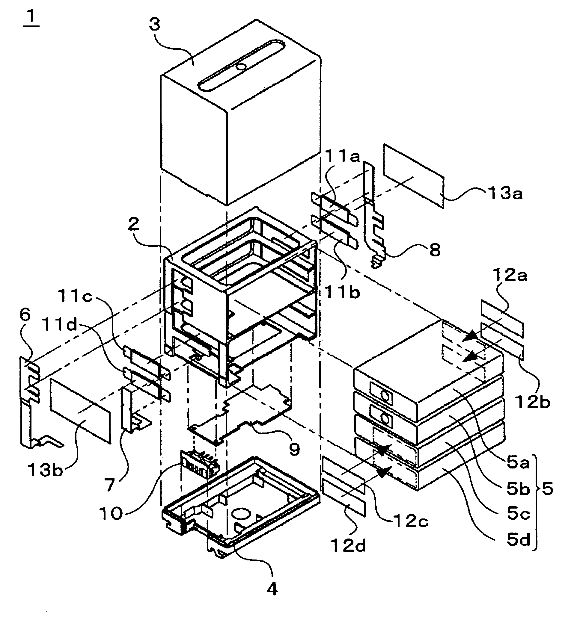
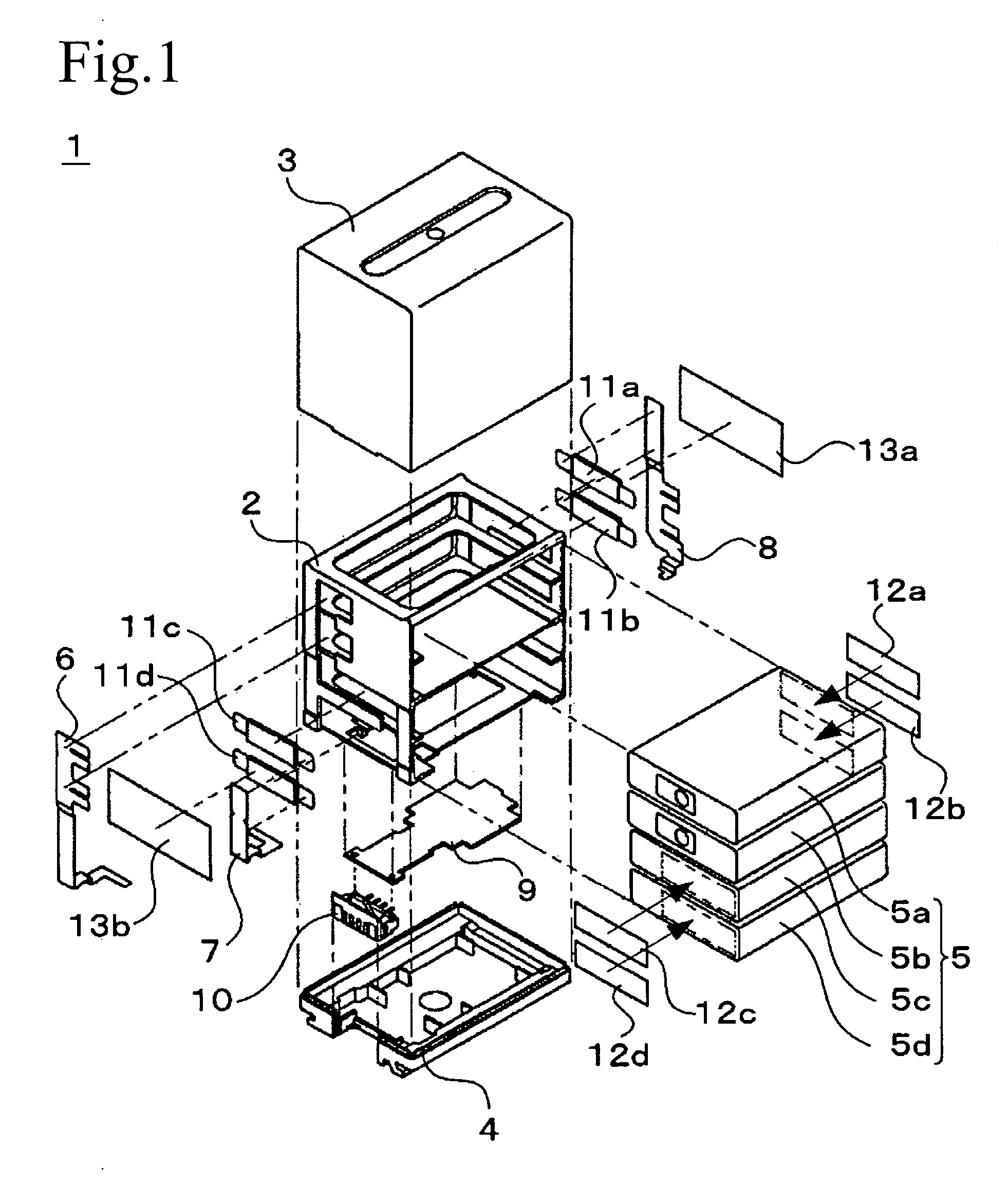
[0023] The following paragraphs will describe embodiments of the present invention referring to the attached drawings. FIG. 1 shows an exemplary configuration of a battery pack according to one embodiment of the present invention. Reference numeral 1 denotes a battery pack used as a power source for driving electronic devices such as video camera. It is to be noted that FIG. 1 is an exploded view of the battery pack 1, wherein the individual components are combined in the direction, indicated by the two-dot chain lines.

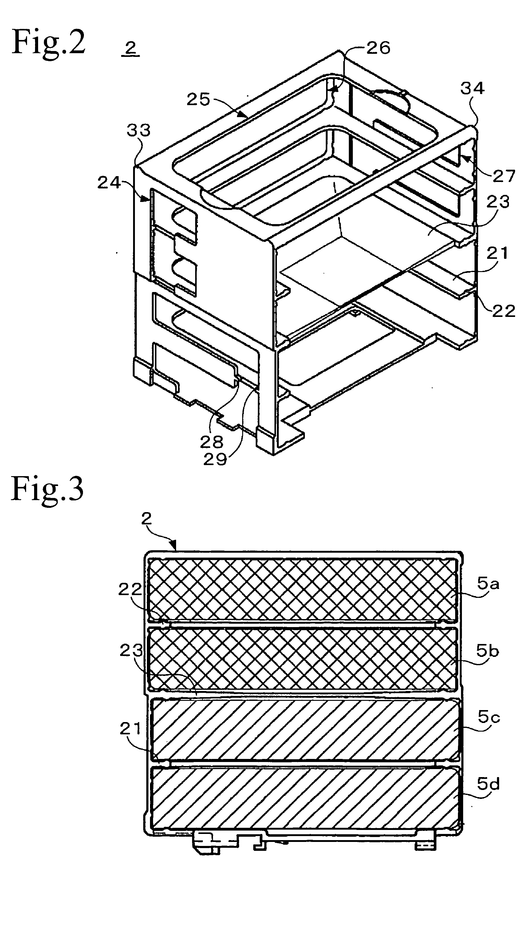
[0024] The battery pack 1 is configured so that a partition member 2 is housed in a case composed of an upper case 3 and a lower case 4. The upper case 3 is a component constituting the upper portion of the case, and the lower case 4 is a component constituting the lower portion of the case. The upper case 3 and the lower case 4 are bonded by welding or with an adhesive so as to make the inner portion of the case tightly sealed. The partition member 2 is configured ...


PUM


Abstract

A battery pack is provided, which can be assembled easily and has a high reliability. In a case of the battery pack 1 constituted by an upper case 3 and a lower case 4, a plurality of box-shaped cells 5 and a partition member 2 are housed. The partition member 2 supports the cells in stacked manner as being spaced from each other, and has an insulating member for insulating between a cell 5b and a cell 5c, which are electrically connected in parallel. The partition member is further provided with the cells 5, a positive electrode 6, a negative electrode 7, an intermediate tub 8, and a guide for aligning the upper case 3 and the lower case 4.

Description

CROSS REFERENCES TO RELATED APPLICATIONS [0001] The present document is based on Japanese Priority Document JP 2004-007470, filed in the Japanese Patent Office on Jan. 15, 2004, the entire contents of which being incorporated herein by reference. BACKGROUND OF THE INVENTION [0002] 1. Filed of the Invention [0003] The present invention relates to a battery pack, and in particular to a battery pack having, housed therein, a plurality of cells, individually configured by housing an electrode stack and an electrolyte in a box-shaped housing, in a stacked manner. [0004] 2. Description of Related Art [0005] In recent trends in downsizing of electronic devices, various batteries used for the electronic devices are also becoming small, having a variety of shapes. Among others, box-shaped lithium ion battery is widely used to mobile phones, notebook-type personal computers and so forth because it can be raised in the energy density. [0006] Battery capacity and voltage adaptive to a wide rang...

Claims


Application Information

Patent Timeline
IPC IPC(8): H01M6/42H01M10/00H01M50/112H01M50/209H01M50/529
CPCH01M2/0242H01M2/1061H01M10/5055H01M10/5032H01M10/504H01M2/24H01M10/653H01M10/647H01M10/6555Y02E60/10H01M50/112H01M50/209H01M50/529H01M50/20
Inventor SUGENO, KAZUYATAKESHITA, TOSHIO
Owner MURATA MFG CO LTD
Why Eureka
Try Eureka