Tailored Fischer-Tropsch synthesis product distribution

a technology of fischertropsch and product distribution, applied in the field of fischertropsch synthesis, can solve problems such as difficulty in controlling the products resulting from synthesis

Inactive Publication Date: 2005-09-15
BATTELLE MEMORIAL INST
View PDF26 Cites 44 Cited by
  • Summary
  • Abstract
  • Description
  • Claims
  • Application Information

AI Technical Summary

Benefits of technology

[0020] A “microchannel” is a channel having at least one dimension of 2 mm, preferably 1 mm, or less. If length is ta

Problems solved by technology

A problem with Fischer-Tropsch synthesis is that it is diff

Method used


Image

  • Tailored Fischer-Tropsch synthesis product distribution
  • Tailored Fischer-Tropsch synthesis product distribution
  • Tailored Fischer-Tropsch synthesis product distribution

Examples


examples

Catalyst Preparation and Characterization

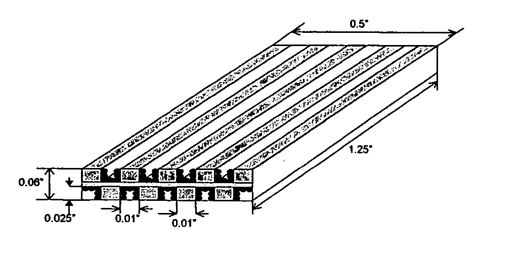
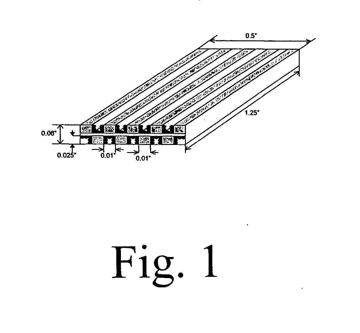
[0042]FIG. 1 is a schematic drawing illustrating the geometry of a monolith catalyst used in the examples. The general dimension of each monolith was 0.5″×0.06″×1.25″. The catalyst substrate 102 was made of aluminum for its high thermal conductivity. The substrate was mini-structured with double-side alternative valleys and peaks. There are 50 valleys for being coated with catalyst ingredients. The width of each valley was 0.01″. Valley depth: 0.025″, Peak width: 0.01″.

[0043] To prepare highly porous catalyst layers on the substrate, a sequential washcoating-impregnation process was applied. The surface of aluminum substrate was first oxidized in air at 550° C. to enhance the adhesion to catalyst layers. A solution with optimized rheological properties was used to achieve uniform coats with desired porosities. PQ Al2O3 (Nyacol) was mixed with poly block copolymer, Pluronic F-127 (HO(CH2CH2O)106(CH2CH(CH3)O)70(CH2CH2O)106H) and ethyl alcoho...


PUM

PropertyMeasurementUnit
Temperatureaaaaaaaaaa
Lengthaaaaaaaaaa

Abstract

Novel methods of Fischer-Tropsch synthesis are described. It has been discovered that conducting the Fischer-Tropsch synthesis over a catalyst with a catalytically active surface layer of 35 microns or less results in a liquid hydrocarbon product with a high ratio of C5-C20:C20+. Descriptions of novel Fischer-Tropsch catalysts and reactors are also provided. Novel hydrocarbon compositions with a high ratio of C5-C20:C20+ are also described.

Description

RELATED APPLICATION [0001] In accordance with 35 U.S.C. sect. 119(e), this application claims priority to U.S. Provisional Application No. 60 / 493,094, filed Aug. 5, 2003.[0002] This invention was made with Government support under Contract DE-AC0676RLO1830 awarded by the U.S. Department of Energy. The Government has certain rights in the invention.FIELD OF THE INVENTION [0003] This invention relates to Fischer-Tropsch synthesis and especially Fischer-Tropsch synthesis of liquid hydrocarbons. INTRODUCTION [0004] In Fischer-Tropsch synthesis, liquid hydrocarbon fuels are produced from lighter gases. This process was first put to large-scale industrial use by Germany during World War II. Since that time, many chemists and chemical engineers worked to develop improvements to the process. There continues to be intense academic and commercial interest in improving Fischer-Tropsch synthesis because it offers a source of liquid hydrocarbon fuels in addition to the increasingly costly proces...

Claims


Application Information

Patent Timeline
IPC IPC(8): C07C27/06C07C27/26
CPCB01J19/0093B01J2219/00835C10G2/333C10G2/332B01J2219/0086Y02P20/141
Inventor WANG, YONGCAO, CHUNSHELI, XIAOHONG SHARIELLIOTT, DOUGLAS C.
Owner BATTELLE MEMORIAL INST
Why Eureka
Try Eureka