

Vehicle control system and method of controlling such
- Summary
- Abstract
- Description
- Claims
- Application Information
AI Technical Summary
Benefits of technology
Problems solved by technology
Method used
Image

Examples
Embodiment Construction
[0032] One basic feature of the present invention is to further develop the ideas from U.S. Pat. No. 5,513,107, relating to configuration of a vehicle according to a number of preset operating modes. There are two main reasons why selectable configuration of a vehicle by preset operating modes is preferred. Firstly, too many individual configuration possibilities are frustrating and too complicated for the majority of the drivers of such vehicles. Secondly, preset operating modes leaves the control of the vehicle performance and characteristics to the manufacturer, whereby a certain security level, road performance, manoeuvrability and the like can be guaranteed. Throughout this application, the term operating mode is defined in that any two operating modes are distinguished from each other, in that the mode specific settings differ for at least two separate vehicle subsystems.
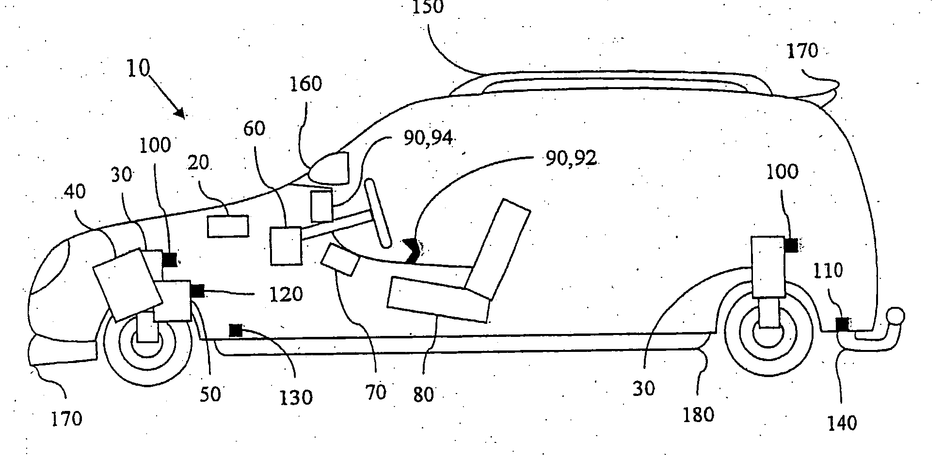
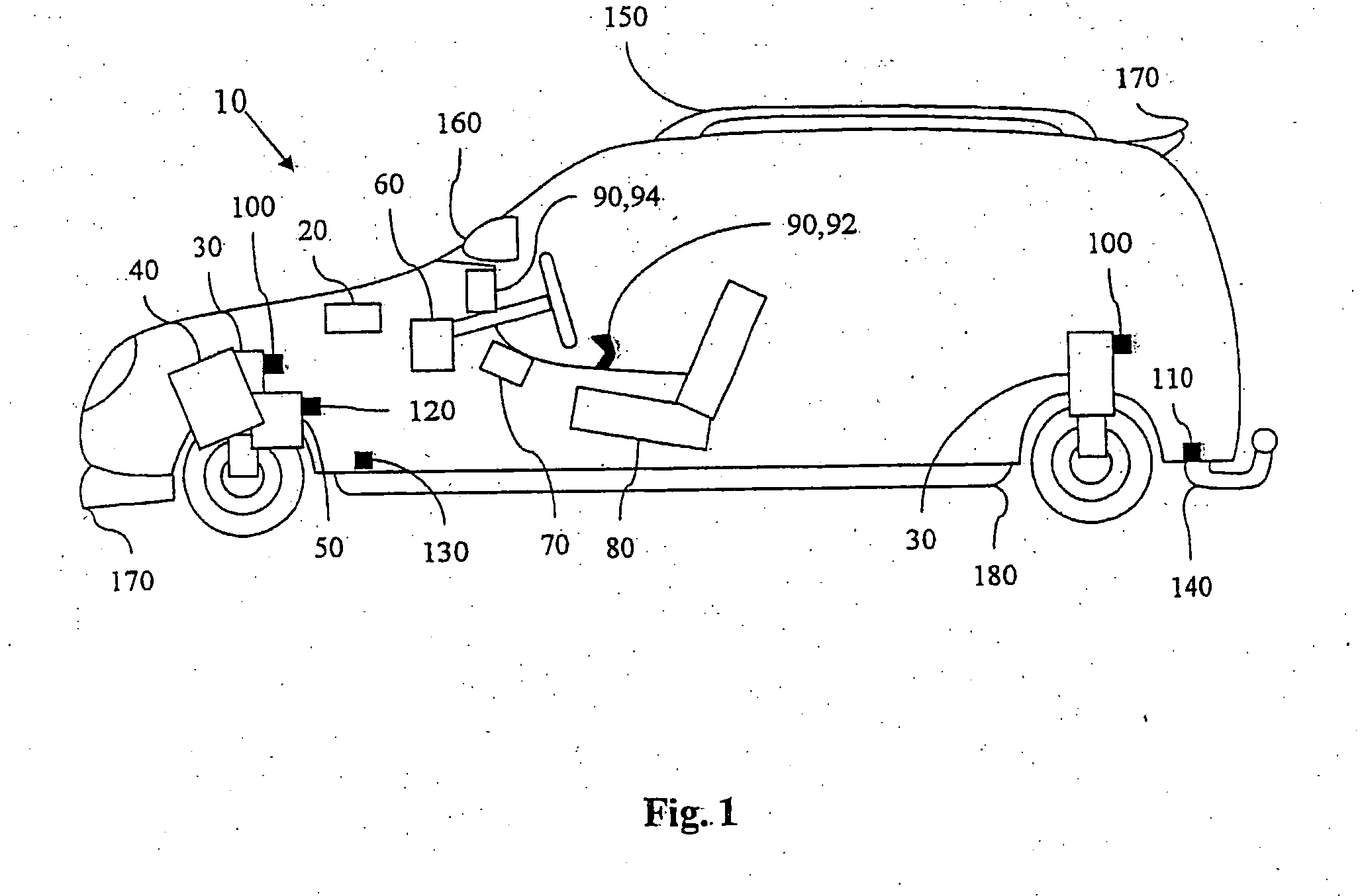
[0033]FIG. 1 schematically shows one embodiment of a vehicle control system 10 according to the present in...
PUM
 Abstract
Description
Claims
Application Information