Method and device for analyzing software error

a software error and analysis method technology, applied in software testing/debugging, error detection/correction, instruments, etc., can solve the problems of unrealistic cost planning of measures, hundreds or a large number of bugs discovered in system test processes,

Inactive Publication Date: 2005-09-15
PANASONIC CORP
View PDF6 Cites 24 Cited by
  • Summary
  • Abstract
  • Description
  • Claims
  • Application Information

AI Technical Summary

Benefits of technology

[0016] As has been described, according to the bug analysis method and device of the present invention, problems of a project can be quantitatively understood. Furthermore, measure planning can be effectively performed by conducting a search, based on examples, for an appropriate measure for each problem of a project.

Problems solved by technology

However, the known technique has the following problems.
In many cases, hundreds or a large number of bugs are discovered in a system test process, i.e., a lower process of development in a software development project.
However, it is not realistic in terms of costs to plan a measure for every single bug in a software development process to prevent the occurrence of the same type of bugs, and also to implement the measure.

Method used


Image

  • Method and device for analyzing software error
  • Method and device for analyzing software error
  • Method and device for analyzing software error

Examples


Embodiment Construction

[0024] Hereinafter, embodiments of the present invention will be described with reference to the accompanying drawings. Preferred embodiments described in the following are not more than examples of the present invention and no way intended to limit the present invention and application or use of the present invention.

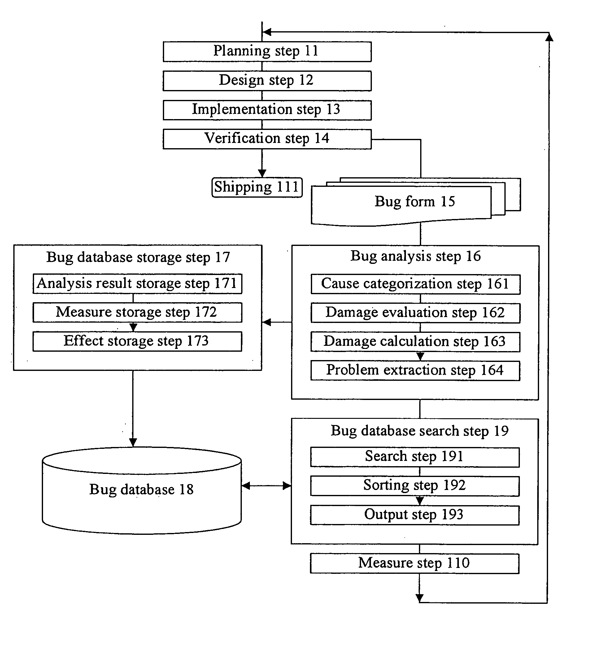
[0025] (1) Software Development Process

[0026]FIG. 1 is a flow chart showing a software development process using a device for analyzing software errors according to one embodiment of the present invention. In general, a software development process can be described with a so-called waterfall model in which development process proceeds in one direction. The waterfall model includes a planning step 11, a design step 12, an implementation step 13 and a verification step 14. It should be noted that a spiral model in which perfection of a system is improved by repeating the design step 12, the implementation step 13 and the verification step 14 while development process p...


PUM


Abstract

In a cause categorization step, bugs are categorized according to technical causes. In a damage evaluation step, how many steps the process has turned back due to a bug is measured. In a damage calculation step, damages are calculated for each bug technical cause. In a problem extraction step, a technical cause of which the damage is large is chosen as a problem. Then, in the bug database search step, a search for a measure for the bug technical cause extracted as a problem is performed with reference with a bug database so as to indicate an appropriate measure for a project.

Description

CROSS-REFERENCE TO RELATED APPLICATION [0001] The disclosure of Japanese Patent Application No. 2004-26351 filed on Feb. 3, 2004 including specification, drawings and claims are incorporated herein by reference in its entity. BACKGROUND OF THE INVENTION [0002] The present invention relates to bug analysis in software development processes, and particularly relates to bug analysis method and device which are helpful to measure planning in a software development process based on technical causes for bugs and damage of bugs on the progress of a project. [0003] In a known software development project, there has been used a quality problem follow-up method and a support system which provide support for preventing re-occurrence of an inconvenience that has once occurred, in view of quality management (e.g., see Japanese Laid-Open Publication No. 2003-187069). SUMMARY OF THE INVENTION [0004] However, the known technique has the following problems. In many cases, hundreds or a large number ...

Claims


Application Information

Patent Timeline
Patent Type & Authority Applications(United States)
IPC IPC(8): G01R31/28G06F9/44G06F11/36G06F11/00
CPCG06F11/3604
Inventor TAMAKOSHI, YASUSHI
Owner PANASONIC CORP
Why Eureka
Try Eureka