
Eureka
For R&D, Eureka makes reading and utilizing patents & technical documents easy.
Eureka AIR
Designed for self-driven R&D workflows. Generate viable solutions, solve complex R&D challenges, empower your innovation with AI.

Eureka Materials
Designed for material experts only. Revolutionize your material R&D, from search, analyze, to developing new materials.

TechResearch
Generate reliable direction feasibility study reports for your R&D in just a few steps.

TechSeek
Discover and master advanced knowledge NOW. Basics, ideas, possibilities, all at once.

TechMind
As an expert in R&D Theories, TechMind can generates customized viable solutions instantly.

TechRisk
Analyze your overall solution with one click, know your potential R&D risks in advance.

TechMonitor
Get weekly tech updates, stay abreast of the latest tech innovations and key insights.
Diagnostic apparatus for variable valve control system
- Summary
- Abstract
- Description
- Claims
- Application Information
AI Technical Summary
Benefits of technology
Problems solved by technology
Method used
Image

Examples
first embodiment
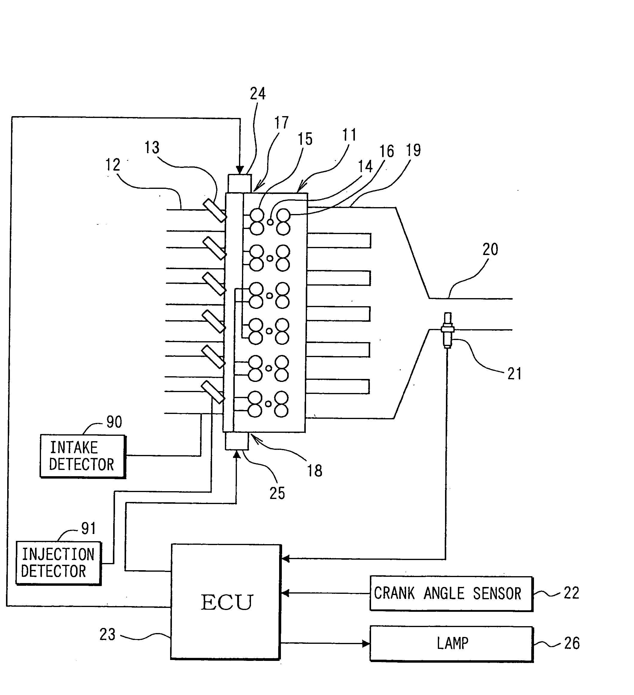
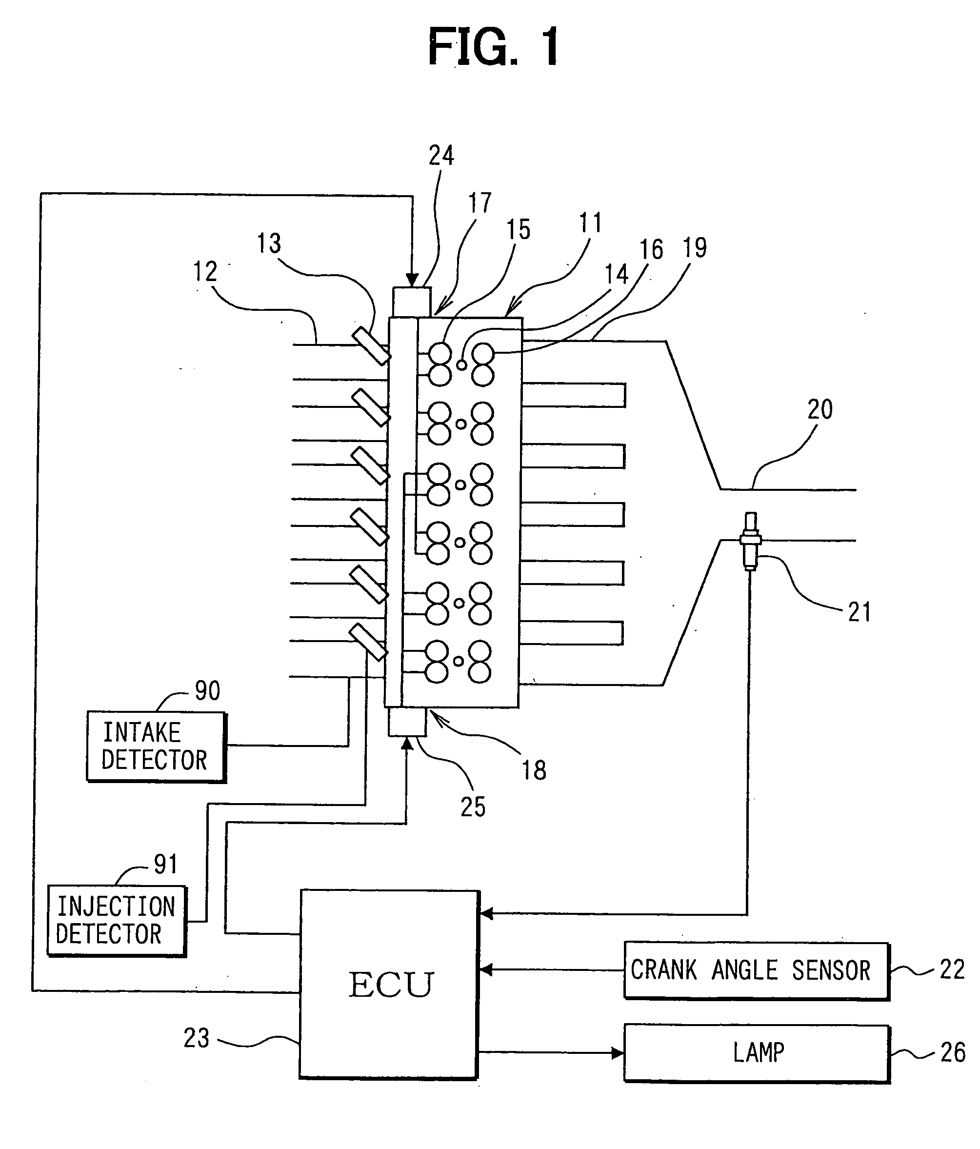
[0035] In an engine control system shown in FIG. 1, an internal combustion engine, for example, a series 6-cylinder engine 11 has six cylinders including a first cylinder to a sixth cylinder. Fuel injection valves 13, which jet fuel, are respectively mounted in the vicinity of intake ports of intake manifolds 12 of respective cylinders of the engine 11. Ignition plugs 14 are mounted to each cylinder on a cylinder head of the engine 11, and spark discharge of the respective ignition plugs 14 causes ignition of fuel-air mixture in the cylinders.
[0036] Besides, variable intake valve lift devices 17, 18 for two systems (two cylinder groups) are mounted to the engine 11. The variable intake valve lift device 17 for one of the systems varies lift of intake valves 15 of the cylinder group (A group) including such as the first, second, and fourth cylinders. The variable intake valve lift device 18 for the other of the systems varies lift of intake valves 15 of the cylinder group (B group) ...
second embodiment
[0087] In the second embodiment, an abnormality region determining routine shown in FIG. 9 is executed. The abnormality region determining routine corresponds to STEP 205 shown in FIG. 4. In the abnormality region determining routine, a variable intake valve lift device of one of two A / B cylinder groups out of the variable intake valve lift devices 17, 18 of the cylinder groups is forcedly modified in control mode. It is determined whether the variable intake valve lift device of the cylinder group, which is forcedly modified in control mode, normally operates, on the basis of the magnitude relation of air-fuel ratio estimate values of respective cylinders, when the control mode is modified. That is, it is determined whether the valve lift characteristics normally changes. It is determined that which of the variable intake valve lift devices of the cylinder groups is abnormal, on the basis of results of determination.
[0088] First, it is determined in STEP 401 whether control modes ...
third embodiment
[0105] As shown in FIG. 10, an air cleaner 113 is provided in an upstream-most region of an intake pipe 112 of an internal combustion engine 11. An air flowmeter 114 for detection of an intake air quantity Q is provided on a downstream side of the air cleaner 113. A throttle valve 115 is provided on a downstream side of the air flowmeter. An opening degree of the throttle valve 115 is regulated by a motor 110. A throttle opening-degree sensor 116 is provided for detection of a throttle opening degree.
[0106] Further, as shown in FIG. 11, a variable intake passage device 135 (intake efficiency varying means) is provided on the downstream side of the throttle valve 115. The variable intake passage device 135 varies a length of an intake passage extending from the throttle valve 115 to a surge tank 117. A primary valve 136 and a secondary valve 137 are provided in the variable intake passage device 135. Opening / closing of the primary valve 136 and the secondary valve 137 is switched ov...
PUM
 Abstract
Description
Claims
Application Information
 - R&D Engineer
- R&D Manager
- IP Professional
- Industry Leading Data Capabilities
- Powerful AI technology
- Patent DNA Extraction
Browse by: Latest US Patents, China's latest patents, Technical Efficacy Thesaurus, Application Domain, Technology Topic, Popular Technical Reports.
© 2024 PatSnap. All rights reserved.Legal|Privacy policy|Modern Slavery Act Transparency Statement|Sitemap|About US| Contact US: help@patsnap.com