Coil design for magnetic pulse welding and forming

a technology of magnetic pulse welding and forming coils, which is applied in the field of magnetic pulse welding and forming devices, can solve the problems of inability to join parts that form a closed loop, the closed coil design has imposed a significant limitation on mpw technology, and the mpw process may require a much higher repulsion force to generate sufficient velocity for bonding, etc., to achieve the effect of preventing arcing between such coils, quick opening/closed, and reducing mechanical wear coils

Inactive Publication Date: 2005-09-22
ENG MECHANICS OF COLU
View PDF4 Cites 24 Cited by
  • Summary
  • Abstract
  • Description
  • Claims
  • Application Information

AI Technical Summary

Benefits of technology

[0017] An advantage of the present invention is that the open / split coil design allows the device to be quickly opened / closed for loading / unloading of workpieces therewithin.
[0018] Another advantage of the present invention is that the individual coil sections of the split coil design are both physically protected and electrically insulated from one another by the presence of an insulating layer mounted at the interface between them. The electrical power input of each coil section can be independently controlled. As a result of the presence of such an insulating layer, there is reduced mechanical wear of the coils, and arcing between such coils is prevented.
[0019] A further advantage of the present invention is that, while currents from the individual coil portions are kept separate from one another, currents within a given coil section or portion are uninterrupted and, when the sections are operatively located relative to each other, their currents together form a unidirectional flow path proximate the open workpiece zone created therewithin. This unidirectional current flow path permits the required magnetic excitation for successful magnetic pulse welding or forming to occur.
[0020] An added advantage of the present invention is that the openable design can potentially accommodate relatively complex weld part configurations, especially when considering that workpiece zone cross-sections that are other than circular in cross-section (e.g., polygonal) may potentially be employed. The advantage of independently controllable coil sections in terms of electrical power input is evident when joining parts with non-circular cross-sections. For example, when certain area of the parts need more intensified magnetic fields and higher magnetic forces, the power input of the corresponding and relevant coil section can be adjusted to higher level.
[0021] Another advantage of the present invention is the use of coil sections in this invention constructed of massive high-strength conductors. They are more easily manufactured and maintained than prior multi-turn solenoid coils.
[0022] An even yet additional advantage of the present invention is that the open / split coil design is amenable to mass production of MPW workpieces, while the presence of insulating interface material between the coil sections allows for the device to have a suitable service lifetime.

Problems solved by technology

247-252, (2000); Daehn, G S “High Velocity Sheet Metal Forming: State of the Art and Prognosis for Advanced Commercialization.”) However, the MPW process may require a much higher repulsion force to generate sufficient velocity for bonding.
The closed coil design has imposed a significant limitation on MPW technology.
The limitation arises from the inability to join parts that form a closed loop.
For example, in automotive applications, the shapes of hydroformed tubes generally are quite complex.
All to date have met with limited success, not sufficient for production purposes. FIG. 3 illustrates the principle of such a coil design.
The largest drawback of this design is that the conducting interface is easily worn and destroyed during operation.
Two major technical difficulties associated with the conducting interface design are that the contact needs to carry ˜1 mega-amp of current without excessive heating during the 100 microseconds that it takes to make the weld; and the contact at the conducting interface has to work ‘perfectly’ without any air gaps that could result in ‘arcing’ during operation.
The trial of the coil design has indicated that it could not be used in the production environment.
While the interface worked very successfully for about 100 trials, the wear in the contact surface increased thereafter leading to ‘arcing’ and other problems in performance.
However, the design does not utilize a magnetic field in the volume encircled by the coil inner surface, where the magnetic field is most intensified.
Therefore, the optimal electrical efficiency of the overall system cannot be achieved by such design.
Since coil segments are electrically connected in series, therefore the power input and magnetic field of the coil segments cannot be controlled independently.

Method used


Image

  • Coil design for magnetic pulse welding and forming
  • Coil design for magnetic pulse welding and forming
  • Coil design for magnetic pulse welding and forming

Examples


Embodiment Construction

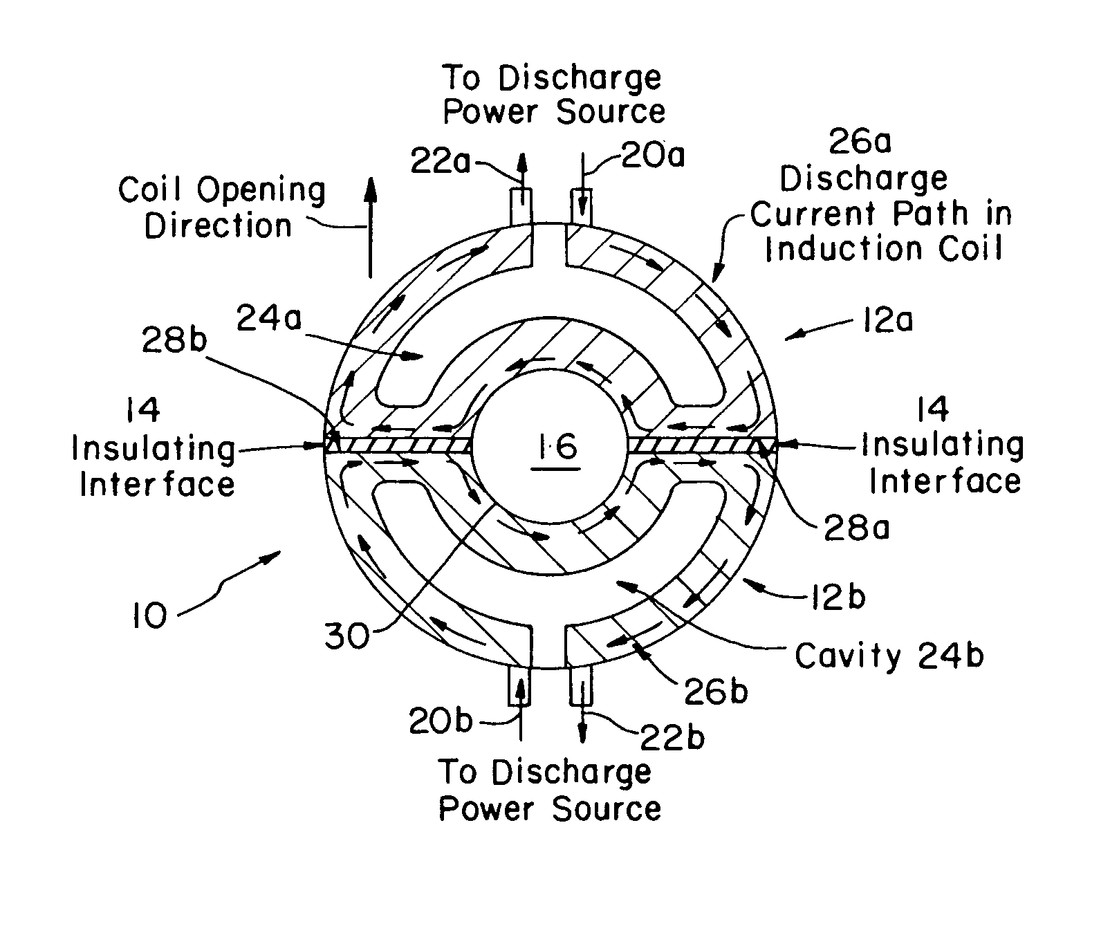
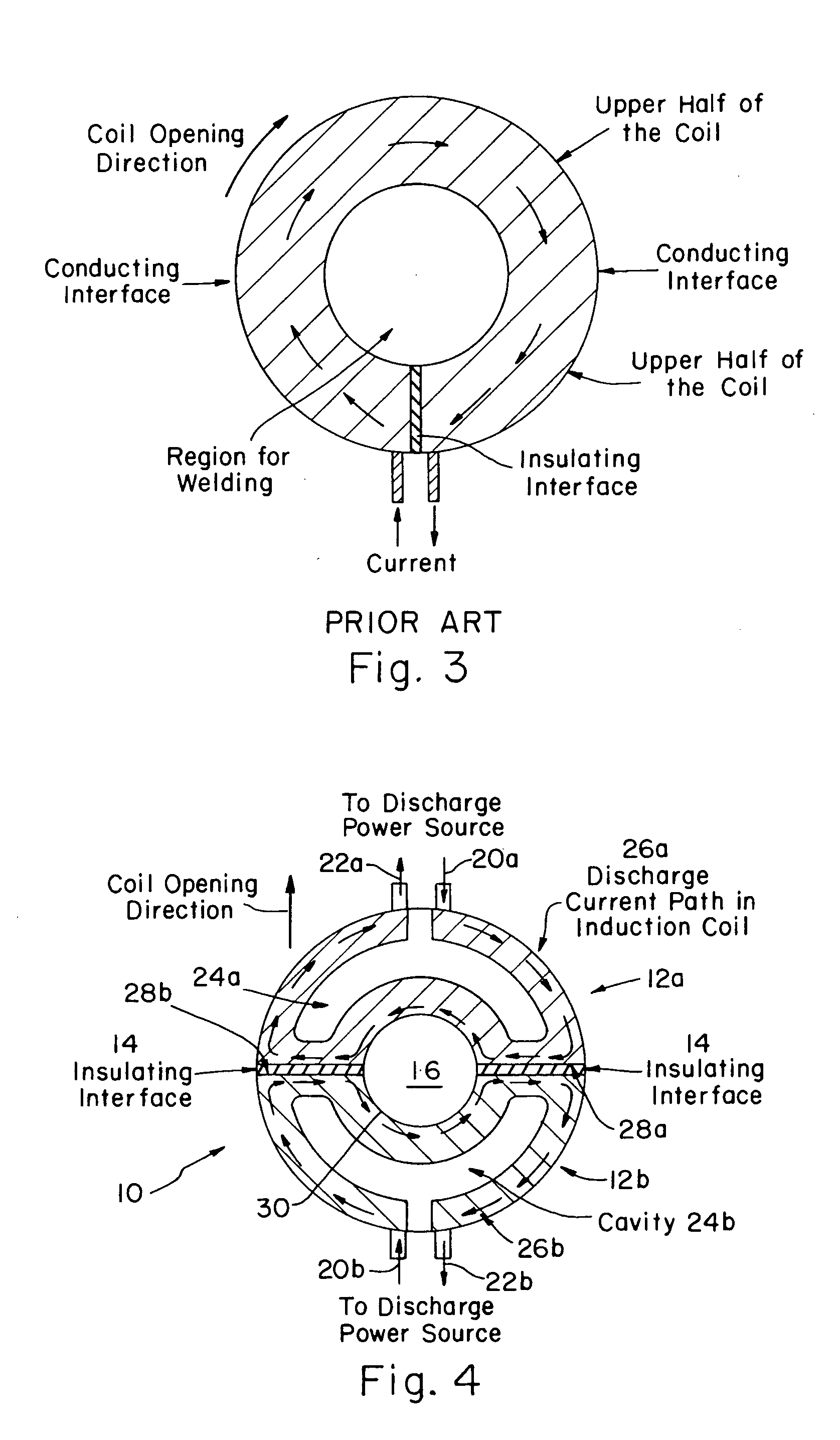
[0030] As seen in FIG. 4 the open (split) coil magnetic pulse welding or forming device 10 of the present invention includes a plurality of coil sections, indicated as coil sections 12A and 12B in the present embodiment; insulating interface 14; and workpiece receiving zone 16.

[0031] Coil sections 12a and 12b are selectably matingly faceable with respect to one another in such a manner so that they may be easily moved into and out of contact with one another. This ability to move relative to one another facilitates loading and unloading of a workpiece assembly (not shown) into and out of workpiece receiving zone 16. Like parts for coil sections 12a and 12b are numbered similarly with parts indicated with a “a” being associated with coil section 12a, and those labeled with a “b” being associated with coil section 12b. Accordingly, coil sections 12a, b include an induction coil member 12a, b; a discharge power source input 20a, b; a discharge power source output 22a, b; a coil cavity...


PUM

PropertyMeasurementUnit
electrical poweraaaaaaaaaa
section induction currentaaaaaaaaaa
induction currentsaaaaaaaaaa

Abstract

A magnetic pulse welding (MPW) or forming (MPF) device is provided having a split coil design, thereby facilitating the opening and closing thereof. As such, part / workpieces can be readily loaded and unloaded with respect thereto. This ability to easily load and unload parts is considered critical to the successful application of MPW technology to mass production environments. The open / split coil design includes a plurality of independent induction coil sections, allowing the device to be quickly opened / closed for loading / unloading of workpieces therewithin.

Description

CONTINUATION DATA [0001] This application hereby claims the benefit under Title 35, United States Codes § 119(e) of any U.S. application Ser. No. 60 / 545,385 filed Feb. 17, 2004, and is hereby incorporated by reference.BACKGROUND OF THE INVENTION [0002] 1. Field of the Invention [0003] The present invention relates to a magnetic pulse welding and forming device, and more particularly to a pulse welding and forming device having a split coil design, thereby allowing opening and closing of the device for workpiece insertion and removal. [0004] 2. Description of the Related Art [0005] The magnetic pulse welding (MPW) or forming (MPF) process utilizes electromagnetic energy to create a metallurgical bond without melting the materials to be joined. First developed in the 1970s in both the US and the former Soviet Union (Epechurin, VP “Properties of bimetal joints produced by magnetic-pulse welding,”Welding Production, Vol. 21, No. 5. pp. 21-24, (1974); Brown, W F; Bandas, J and Olson, N T...

Claims


Application Information

Patent Timeline
Patent Type & Authority Applications(United States)
IPC IPC(8): B21D26/14B23K13/01B23K20/06H05B6/36
CPCB21D26/14B23K13/01H05B6/36B23K2201/06B23K20/06B23K2101/06
Inventor CHENG, WENTAOKRISHNASWAMY, PRABHAT
Owner ENG MECHANICS OF COLU
Why Eureka
Try Eureka