
Resin torque rod and method of producing the same

a torque rod and resin technology, applied in the field of torque rods, can solve the problems of increasing so as to reduce the manufacturing cost of torque rods, simplify the structure of resin molds, and increase the number of torque rods

Inactive Publication Date: 2005-09-22
SUMITOMO RIKO CO LTD
View PDF0 Cites 14 Cited by
  • Summary
  • Abstract
  • Description
  • Claims
  • Application Information

AI Technical Summary

Benefits of technology

[0022] It is therefore one object of this invention to provide a resin torque rod capable of simplifying the structure of the resin mold for forming the resin torque rod, permitting a greater number of torque rods to be obtained per resin mold, and reducing torque rod manufacturing costs. It is another object of the invention to provide a method of producing the resin torque rod of the invention.
[0033] This allows the structure of the resin mold to be simplified, allows the cost of the resin mold to be reduced, allows a greater number of torque rods to be obtained per resin mold, and allows the torque rod manufacturing costs to be reduced.
[0034] The invention is more effective when applied to a resin torque rod in which the first bushing has axially extending voids, particularly a resin torque rod in which the voids pass axially through the rubber elastic body (Second or Third Modes).
[0036] The dividing direction of the molding part for the connecting component in the resin mold, that is, the molding part for the connecting component that connects the first and second bushings, can be readily aligned with the dividing direction of the molding parts for the first and second bushings by making the shape of the connecting component into a suitable shape, such as a cross-shaped, round, elliptical or diamond-shaped cross section. This will allow the resin mold as a whole to have a dividing structure in the axial directions of the first and second bushings.
[0039] Providing such a reinforcing rib can increase the strength of the connecting component when the connecting component has a U- or H-shaped cross section.

Problems solved by technology

Such torque rods also damp vibration between the engine and body.
Meanwhile, in the case of the latter perpendicular type of torque rod, that is, torque rods in which the first and second bushings face each other at right angles, the direction in which the first and second bushing mold parts divide are 90 degrees apart, resulting in a complex mold structure.
The structure of the resin mold 220 is thus inevitably complicated.
The resin mold 220 is thus expensive, and molding operations are complicated, including mold assembly and separation.
The complexity of the resin mold 220 structure results in a fewer number of products (resin torque rods) per resin mold 220, which contributes to greater resin torque rod 200 manufacturing costs.

Method used


Image

  • Resin torque rod and method of producing the same
  • Resin torque rod and method of producing the same
  • Resin torque rod and method of producing the same

Examples


Embodiment Construction

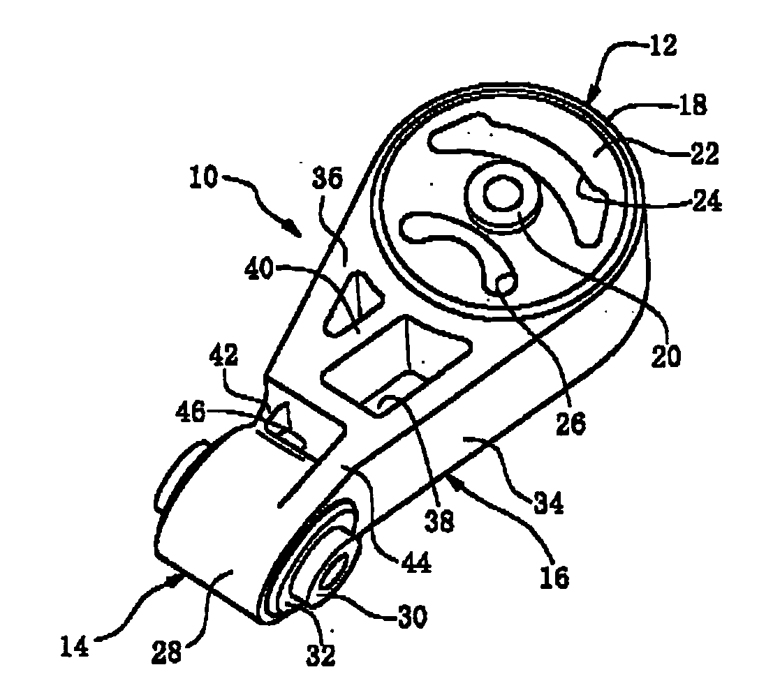
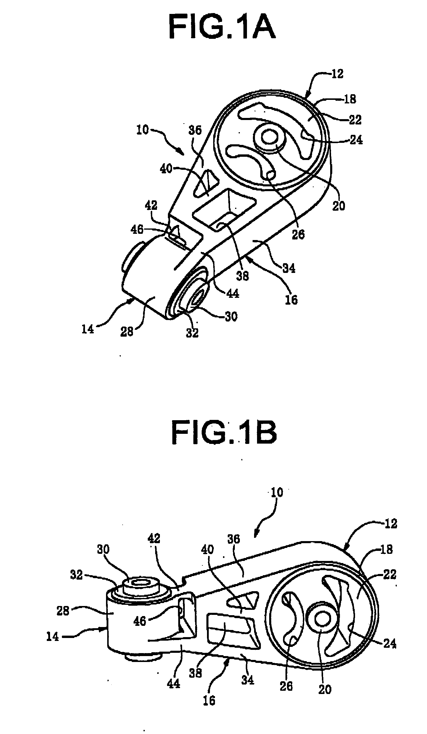
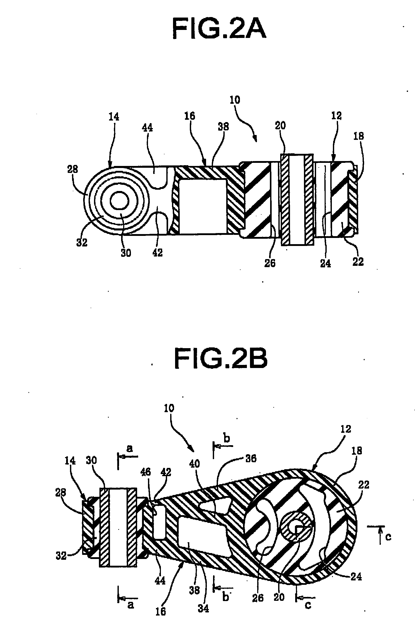
[0054] Referring first to FIGS. 1 and 2, 10 is a torque rod (resin torque rod), comprising a first bushing 12 composed of a larger cylindrical bushing at one end, and a second bushing 14 composed of a smaller cylindrical bushing at the other end. These are joined to each other by a resin connecting component 16. The first bushing 12 and second bushing 14 are disposed facing at right angles to each other. Specifically, their axes are disposed facing at right angles.

[0055] The second bushing 14 and first bushing 12 of the torque rod 10 are elastically joined to the engine and body sides, respectively, for example, to take up torque from the engine in order to control displacement in the engine rolling direction and displacement in the longitudinal direction. The torque rod 10 also damps vibration between the engine and body sides.

[0056] The first bushing 12 comprises a resin outer casing 18 integrally formed with the resin connecting component 16, a metal inner casing 20, and a rubb...


PUM

PropertyMeasurementUnit
weight %aaaaaaaaaa
elasticaaaaaaaaaa
diameteraaaaaaaaaa

Abstract

A resin torque rod including: a first and second bushing disposed at both ends of the resin torque rod, each bushing having a resin outer casing and a rigid inner casing and a rubber elastic body interposed between the outer and inner casings, and a resin connecting component for connecting the first and second bushings, the first and second bushings facing each other at right angles. The rubber elastic body in the second bushing is shaped such that at least outer peripheral portions of axial and faces of the rubber elastic body protrude the same as, or beyond axially outwardly from axial end faces of the resin outer casing of the second bushing, respectively, and that the intermediate portion in an axis-perpendicular direction between the inner casing and outer cuing has a substantially solid shape. A method of producing the resin torque rod is also disclosed.

Description

[0001] The disclosure of Japanese Patent Application No. 2004-081182 filed on Mar. 19, 2004 including the specification, drawings and abstract is incorporated herein by reference in its entirety. BACKGROUND OF THE INVENTION [0002] 1. Field of the Invention [0003] The present invention relates to a torque rod that is interposed between the engine and body of a vehicle to control displacement in the engine rolling direction and the longitudinal direction, as well as to damp vibration between the engine and body. More specifically, the invention relates to a resin torque rod in which outer casings of the first and second bushings as well as a connecting component that connects at both ends with those bushings are made of resin. [0004] 2. Description of the Related Art [0005] Conventionally, torque rods are mounted between the engine and body of a vehicle. These torque rods have first and second bushings at both ends, each of which has an outer and inner casing, with a rubber elastic bo...

Claims


Application Information

Patent Timeline
Patent Type & Authority Applications(United States)
IPC IPC(8): B60G1/00B60K5/12B60K5/00F16F1/38F16F15/08
CPCY10T29/4998F16F1/3849B60K5/12F16F1/3814F16F1/3842F16F15/08
Inventor ENDO, MASAMI
Owner SUMITOMO RIKO CO LTD
Learn More