Method for recharging a battery at the same time it is being used as a power source

Inactive Publication Date: 2005-09-22
GRANT EARL SR
View PDF11 Cites 6 Cited by
  • Summary
  • Abstract
  • Description
  • Claims
  • Application Information

AI Technical Summary

Benefits of technology

[0006] The invention addresses the need to recharge a battery by using a portion of the electrical output, at the same time the battery i

Problems solved by technology

There are many situations in which users of electrical tools, lights, radios, appliances, equipment and other electrically-powered items are unable to connect to

Method used


Image

  • Method for recharging a battery at the same time it is being used as a power source
  • Method for recharging a battery at the same time it is being used as a power source
  • Method for recharging a battery at the same time it is being used as a power source

Examples


Embodiment Construction

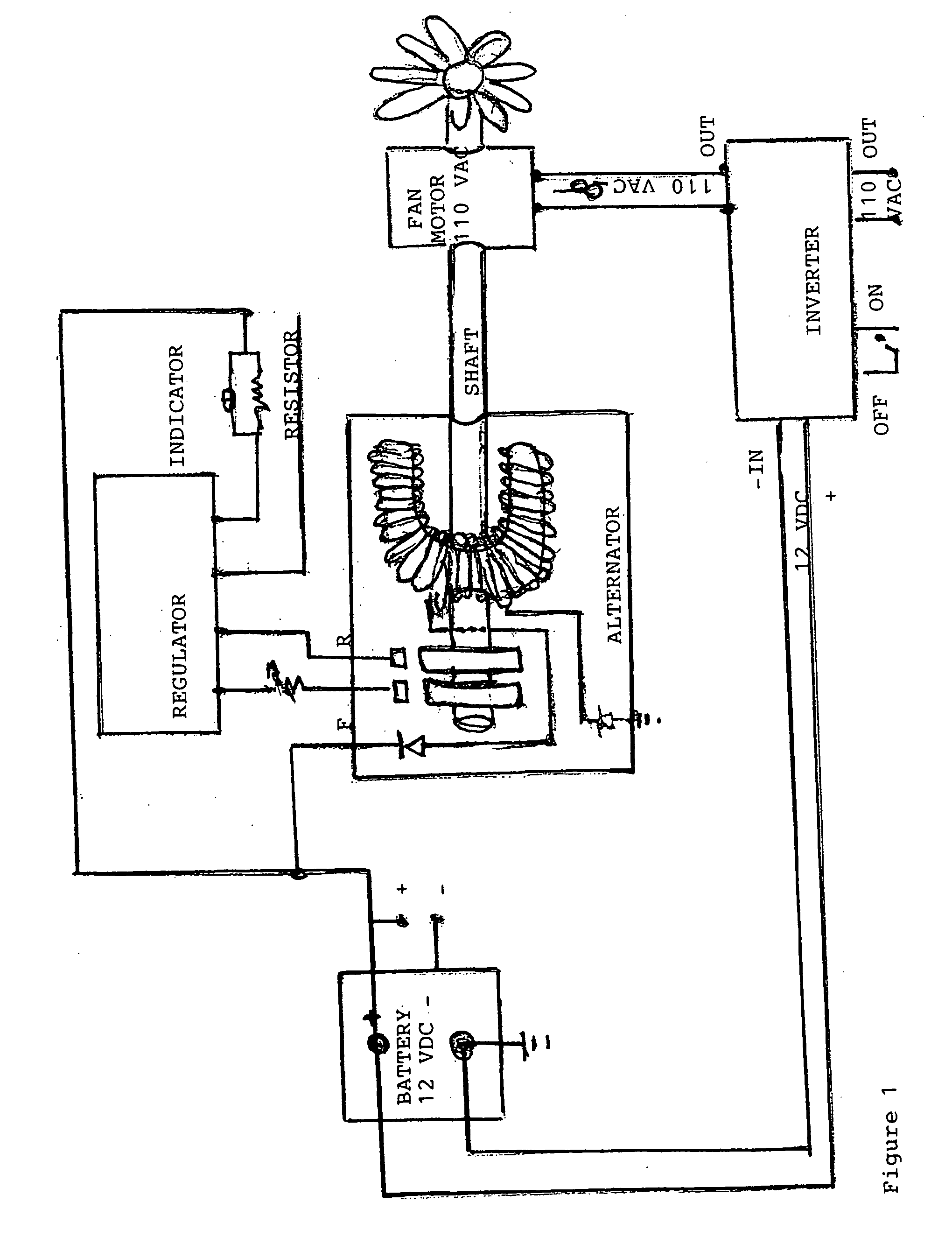
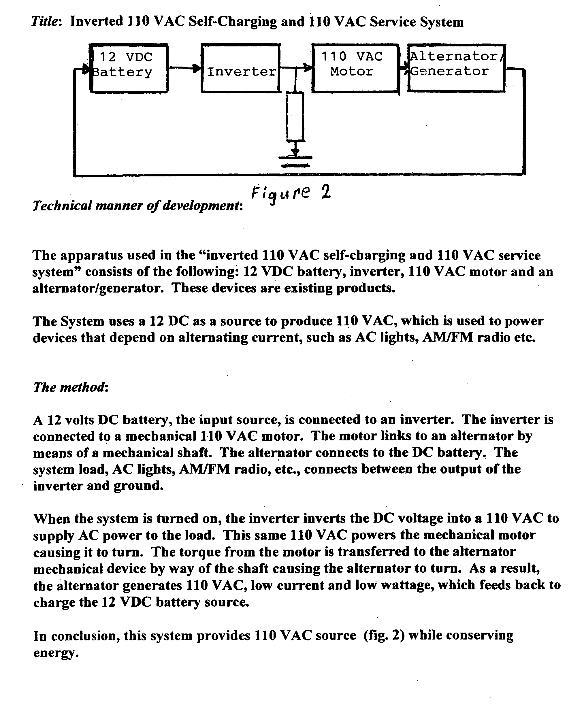
[0010] A DC battery, the input source, is connected to an inverter. The inverter is connected to an AC mechanical motor. The motor is linked to an alternator by means of a mechanical shaft. The alternator connects to the DC battery. The system load, e.g. a power tool, connects to the system between the electrical output of the inverter and ground.

[0011] When the system is activated, the inverter converts DC power from the battery to supply AC power to the load and, at the same time, to the mechanical motor causing it to turn. The torque from the motor is transferred to the alternator by way of the shaft, causing the alternator to turn and to generate low current which feeds back to recharge the battery.

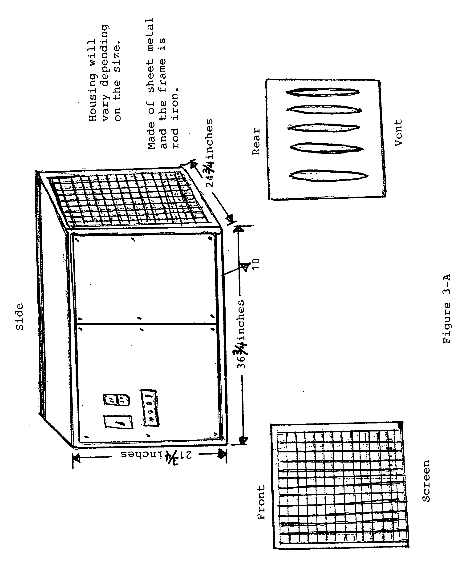
[0012] Aside from the system assembly shown in FIG. 3, all of the components and mechanical apparatus are available commercially. The method of connecting and employing these components and apparatus is new.

PARTS LIST BY NUMBER FOR FIG. 3

[0013]1. Battery [0014]2. Inverter [0015]3. ...


PUM


Abstract

A method for recharging a battery, at the same time it is being used as a power source, by using a portion of the electrical output to operate an alternator to produce low current and low voltage electrical power to recharge the battery.

Description

CROSS-REFERENCE TO RELATED APPLICATIONS [0001] Provisional Application No. 60 / 550,957STATEMENT REGARDING FEDERALLY SPONSORED RESEARCH OR DEVELOPMENT [0002] Not Applicable REFERENCE TO SEQUENCE LISTING, A TABLE, OR A COMPUTER DISK APPENDIX [0003] Not Applicable BACKGROUND OF THE INVENTION [0004] There are many situations in which users of electrical tools, lights, radios, appliances, equipment and other electrically-powered items are unable to connect to a regular source of electrical power. Batteries are used to provide electrical power in such situations either directly to the equipment being used or to a portable generator to which the equipment is connected. However, a battery is not entirely satisfactory as a power source in such situations because it must be frequently recharged. [0005] Relevant U.S. patents are identified below: 5689174November, 1997PachecoRe31156February, 1983Dessert1275201August, 1918Beach2813984November, 1957Dolecki, et al.3719881March, 1973Shibata, et al....

Claims


Application Information

Patent Timeline
IPC IPC(8): H02J7/00H02K53/00
CPCH02K53/00
Inventor GRANT, EARL SR.
Owner GRANT EARL SR
Why Eureka
Try Eureka