Rotation state detecting device and rotation state detecting method
a detection device and rotating state technology, applied in hurricane shutters, door/window protective devices, instruments, etc., can solve the problems of wrong ignition timing of cylinders, inability to detect the rotation direction of toothed wheels,
- Summary
- Abstract
- Description
- Claims
- Application Information
AI Technical Summary
Benefits of technology
Problems solved by technology
Method used
Image
Examples
first preferred embodiment
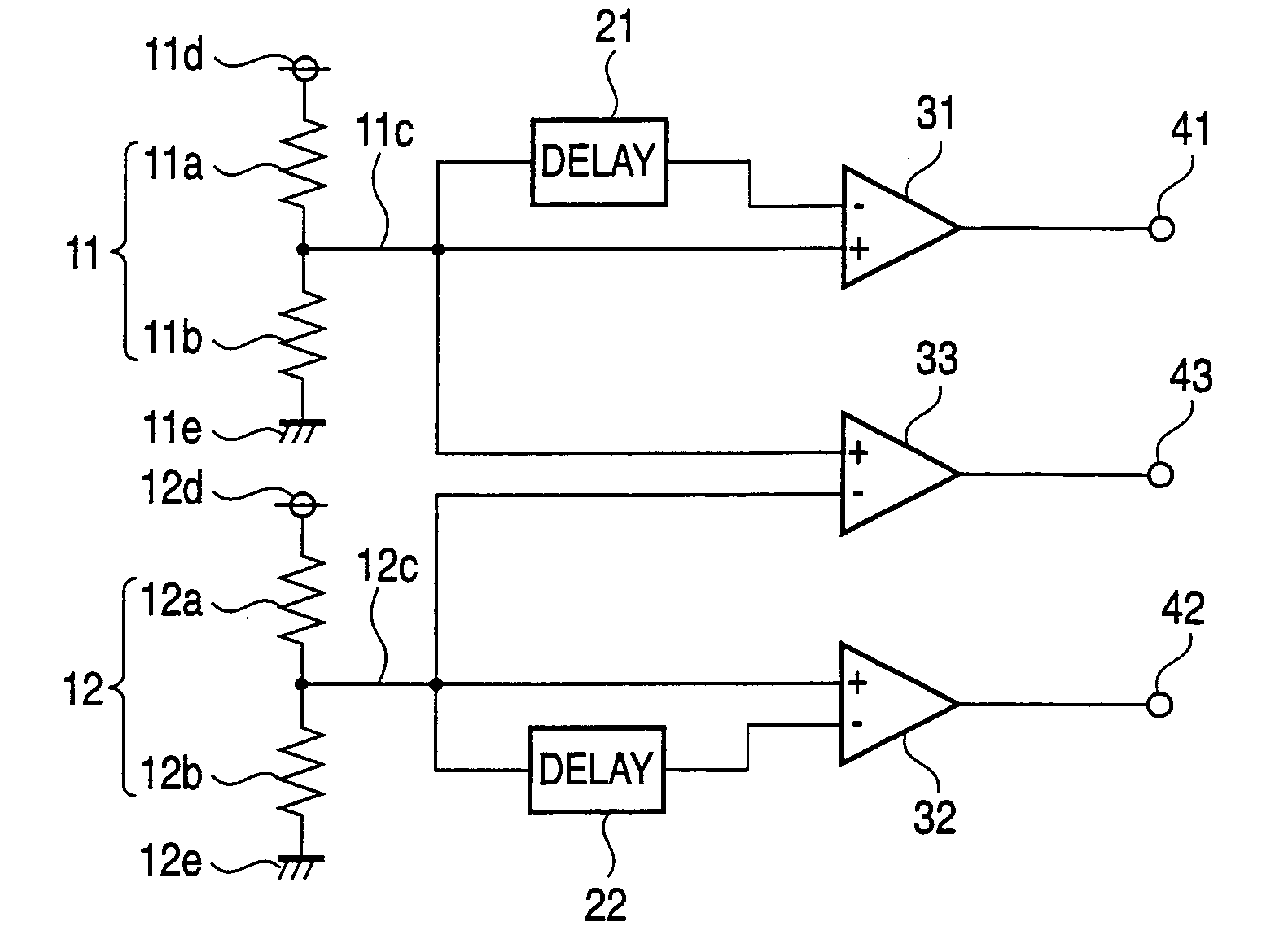
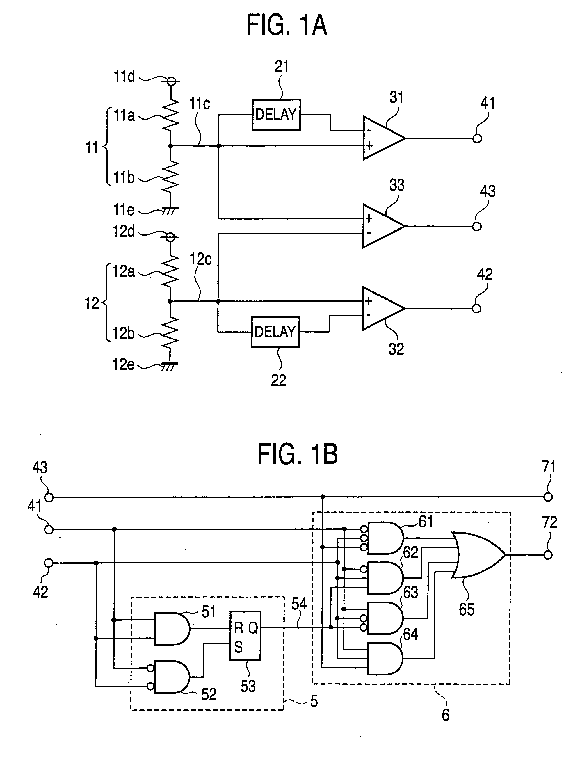
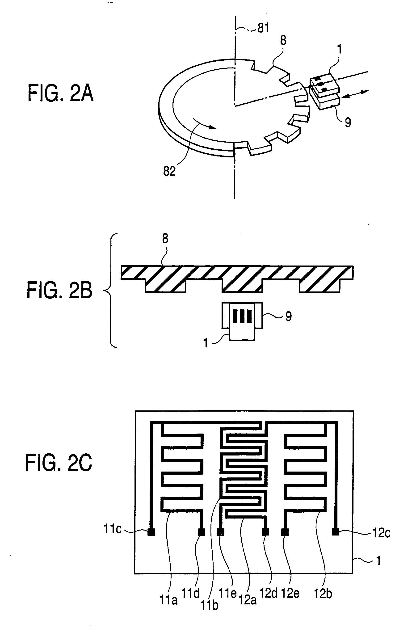
[0023]FIGS. 1A and 1B are block diagrams showing main parts of a first preferred embodiment of a rotation state detecting device according to the invention. FIGS. 2A to 2C are views illustrating the construction of a magnetic circuit used in the rotation state detecting device of the first preferred embodiment, FIG. 2A being a perspective view, 2B a plan view and 2C a view of a pattern of magneto-resistance effect elements. In FIGS. 2A to 2C, a magneto-resistance effect element unit 1 is made up of magneto-resistance effect elements 11a, 11b, 12a and 12b. Referring to FIG. 1, the magneto-resistance effect elements 11a, 11b are connected and form a first bridge circuit 11 having a grounded terminal 11e, a terminal lid to which a constant voltage is applied, and a terminal 11c that outputs a center point voltage. Similarly, the magneto-resistance effect elements 12a, 12b are connected and form a second bridge circuit 12 having a grounded terminal 12e, a terminal 12d to which a constan...
second preferred embodiment
[0043]FIG. 9 is a block diagram showing a main part of a rotation state detecting device according to a second preferred embodiment. Comparators 31, 32 compare center point voltages 11c, 12c with the outputs of delay circuits 21, 22, but to prevent misoperation, respective low pass filters 23, 24 are inserted to remove a noise component from the signals being compared. In FIG. 9, a high-frequency noise component of the center point voltage 11c, 12c outputs is removed with low pass filters 23, 24, and the outputs of the low pass filters 23, 24 are compared with the outputs of delay circuits 21, 22 for delaying those outputs by the comparators 31, 32. Similarly, the outputs of the low pass filters 23, 24 are compared with each other by a comparator 33. As a result, because signals in which noise caused by external disturbances is removed from them are compared, misoperation caused by noise can be suppressed.
[0044] Although in this second preferred embodiment the outputs of the low pa...
third preferred embodiment
[0045]FIG. 10 is a block diagram showing a main part of a rotation state detecting device according to a third preferred embodiment. Whereas in the first preferred embodiment the increasing / decreasing directions of the center point voltages 11c, 12c were detected using delay circuits 21, 22 and comparators 31, 32, alternatively the analog values of the center point voltages 11c, 12c may be converted into digital values with A / D-convertors 25, 26, and these digital values (signals) may be delayed using flip-flop circuits 27, 28 to detect the increasing / decreasing direction. In FIG. 10, the A / D-convertors 25, 26 convert the analog values (signals) of the center point voltages 11c, 12c into digital values (signals). The flip-flop circuits 27, 28 delay the center point voltages 11c, 12c converted to digital values by 1 clock period.
[0046] Logic circuits 34, 35 compare the digital values of the center point voltages 11c, 12c (the outputs of the A / D-convertors 25, 26) with the digital va...
PUM
 Abstract
Description
Claims
Application Information
 - R&D
- Intellectual Property
- Life Sciences
- Materials
- Tech Scout
- Unparalleled Data Quality
- Higher Quality Content
- 60% Fewer Hallucinations
Browse by: Latest US Patents, China's latest patents, Technical Efficacy Thesaurus, Application Domain, Technology Topic, Popular Technical Reports.
© 2025 PatSnap. All rights reserved.Legal|Privacy policy|Modern Slavery Act Transparency Statement|Sitemap|About US| Contact US: help@patsnap.com


