Radar apparatus
a radar and beam forming technology, applied in the direction of instruments, measurement devices, vehicle components, etc., can solve the problems of large number of antenna elements, inability to guarantee the advantages of the conventional dbf radar apparatus in the radar apparatus, and lack of consideration of the antenna system
- Summary
- Abstract
- Description
- Claims
- Application Information
AI Technical Summary
Benefits of technology
Problems solved by technology
Method used
Image
Examples
first embodiment
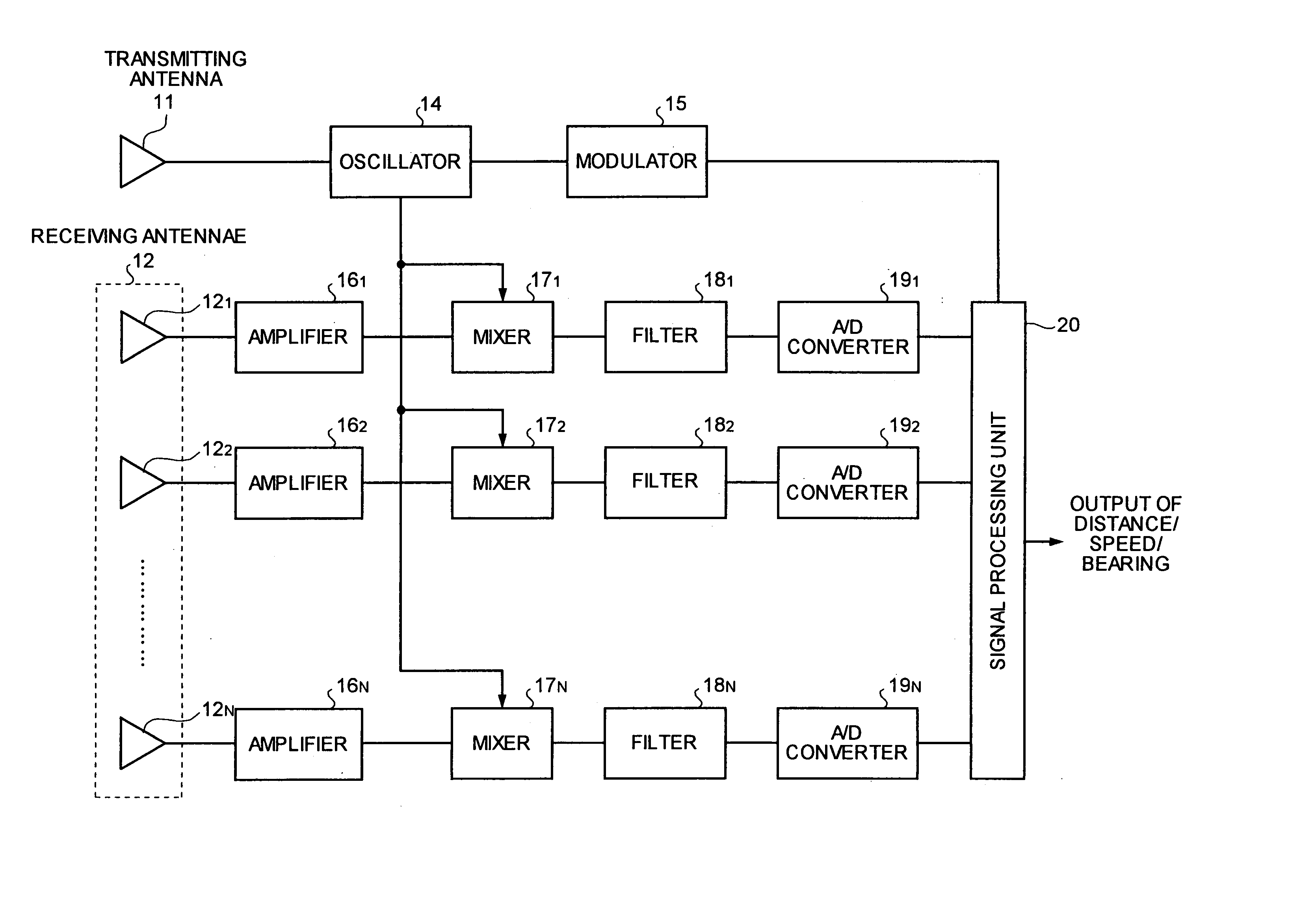
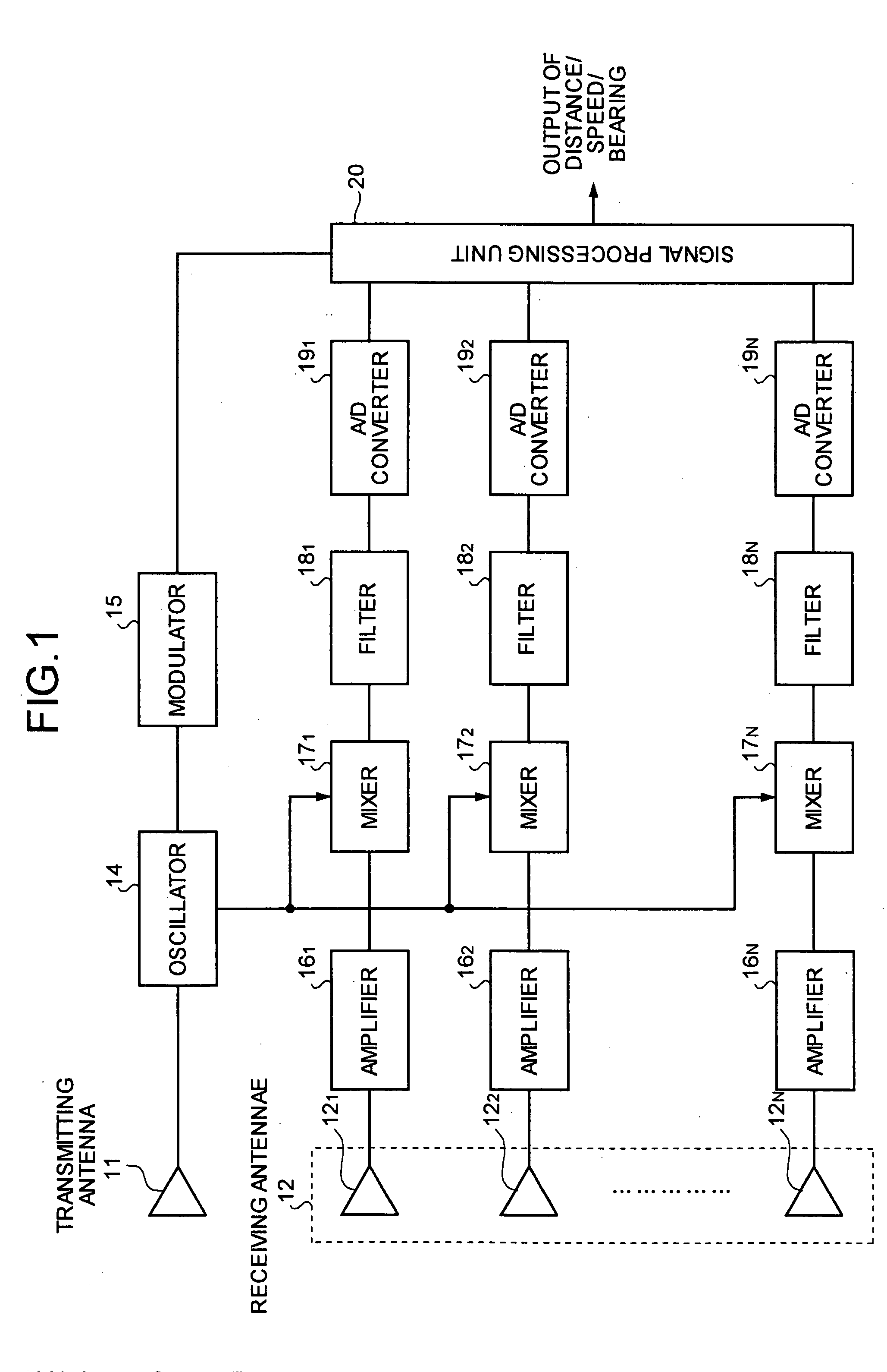
[0032]FIG. 1 is a block diagram of a radar apparatus according to the present invention. A transmitting system of the radar apparatus in FIG. 1 includes a transmitting antenna 11, an oscillator 14, and a modulator 15. A receiving system includes a plurality of receiving antennae 12 (121, 122, . . . 12N), amplifiers 16 (161, 162, . . . 16N), mixers 17 (171, 172 . . . 17N), filters 18 (181, 182, . . . 18N), A / D converters 19 (191, 192, . . . 19N), and a signal processing unit 20. The amplifiers 16 are connected to corresponding receiving antennae 12. The mixers 17 downconvert each of the signals (reception signals) output from the amplifiers 16, based on the signals (local signals) fed from the oscillator 14. The filters 18, connected to the mixers 17, put a bandwidth constraint on the downconverted signals. The A / D converters 19, connected to the filters 18, convert the reception signals from analog signals to digital signals, after the reception signals are subjected to bandwidth co...
second embodiment
[0056] Similar to the second embodiment, it is possible to use different types of sub-array structures and different process modes in the present embodiment, and obtain similar results.
[0057]FIG. 8 is a block diagram of a radar apparatus according to a third embodiment of the present invention. The radar apparatus shown in FIG. 8 includes a modulation controller 22 between the modulator 15 and the signal processing unit 20. The rest of the structure is identical to the structure according to the first embodiment shown in FIG. 1. The parts in the third embodiment that are the same as or equivalent to the parts in the first embodiment are assigned the same reference numerals.
third embodiment
[0058] When fixed objects or medium and long distance target objects are present in the direction-of the target object, or when a strong noise source is present even though not in the direction of the target object, the filters 18 may fail to filter out signals from these objects, thereby resulting in detecting a wrong object rather than the intended target. Hence, in the radar apparatus the modulation controller 22 provides control to vary various parameters of the modulated signals output from the modulator 15, based on the control exerted by the signal processing unit 20. For the FM-CW radar apparatus, the parameters of the modulated signals include frequency shift width, repetition cycle, etc. For the pulse-Doppler radar apparatus, the parameters of the modulated signals include pulse repetition frequency, pulse width, etc.
[0059] The functioning of the radar apparatus according to the third embodiment is explained next, using the FM-CW radar as an example. The principle of an F...
PUM
 Abstract
Description
Claims
Application Information
 - R&D
- Intellectual Property
- Life Sciences
- Materials
- Tech Scout
- Unparalleled Data Quality
- Higher Quality Content
- 60% Fewer Hallucinations
Browse by: Latest US Patents, China's latest patents, Technical Efficacy Thesaurus, Application Domain, Technology Topic, Popular Technical Reports.
© 2025 PatSnap. All rights reserved.Legal|Privacy policy|Modern Slavery Act Transparency Statement|Sitemap|About US| Contact US: help@patsnap.com


